Supercharged power transmission assembly for suspension shaft centrifugal supercharger and centrifugal supercharger

A technology of power transmission and supercharger, which is applied in the direction of transmission, engine components, machines/engines, etc. It can solve the problems affecting the supercharging effect, unevenness, uneven air pressure, etc., and achieve the effect of improving air intake and supercharging , Reduce the central axis resonance phenomenon, reduce the effect of friction loss

Active Publication Date: 2017-12-01
HUANGSHI XUANYANZHE POWER TECH
View PDF5 Cites 0 Cited by
  • Summary
  • Abstract
  • Description
  • Claims
  • Application Information

AI Technical Summary

Problems solved by technology

On the one hand, due to factors such as possible slipping of the three pulleys in the belt drive, there is a speed difference in the rotation of the three friction wheels, which leads to unstable rotation of the suspension center shaft, making the air pressure uneven and affecting the boosting effect On the other hand, the three sets of friction wheel components are made of elastic materials, and there will be resonance phenomena caused by unbalanced rotation / support in the support and drive of the central shaft, and there are also problems such as inherent rotation accuracy defects of elastic wheels. These will lead to unstable and uneven rotation of the pulsator, which will affect the air intake and supercharging effect, resulting in large defects in the supercharger

Method used


Image

  • Supercharged power transmission assembly for suspension shaft centrifugal supercharger and centrifugal supercharger
  • Supercharged power transmission assembly for suspension shaft centrifugal supercharger and centrifugal supercharger
  • Supercharged power transmission assembly for suspension shaft centrifugal supercharger and centrifugal supercharger

Examples


Embodiment Construction

[0029] In order to make the object, technical solution and advantages of the present invention clearer, the present invention will be further described in detail below in conjunction with the accompanying drawings and embodiments. It should be understood that the specific embodiments described here are only used to explain the present invention, not to limit the present invention.

[0030] In addition, the technical features involved in the various embodiments of the present invention described below can be combined with each other as long as they do not constitute a conflict with each other.

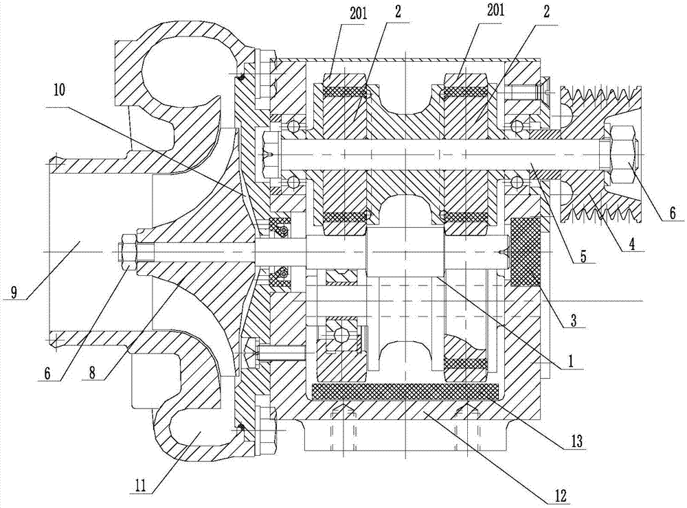
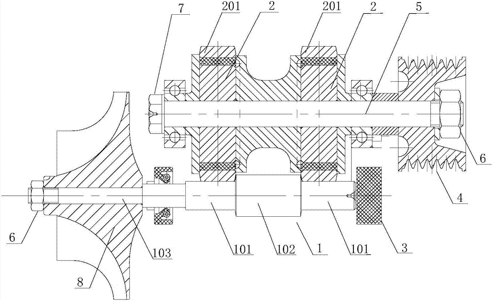
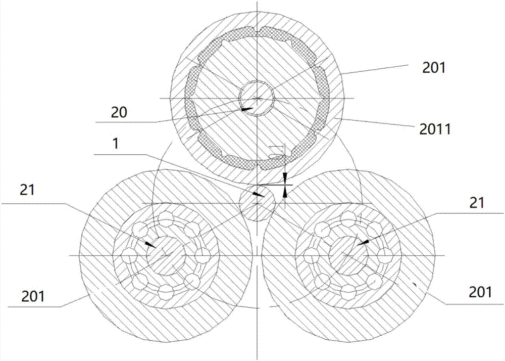
[0031] figure 1 It is a structural schematic diagram of the application of the supercharging power transmission assembly in the suspended shaft centrifugal supercharger according to an embodiment of the present invention; figure 2 for figure 1 Schematic diagram of the structure of the elastic friction wheel set of the supercharged power transmission assembly; image 3 It is a schema...


PUM


Abstract

The invention discloses a supercharged power transmission assembly for a suspension shaft centrifugal supercharger. The supercharged power transmission assembly comprises a plurality of friction wheel groups and a belt wheel in coaxial power connection with one of the friction wheel groups. The end portion of one end of a center shaft of the first friction wheel group stretches out of a box body to be fixedly connected with the belt wheel, the belt wheel is used for being in power connection with an external power unit, and friction wheels of the first friction wheel group are both elastic friction wheels; and at least the friction wheels, close to one end of a centrifugal impeller group, of the second friction wheel group and the third friction wheel group are rigid wheels. The invention further discloses the centrifugal supercharger provided with the supercharged power transmission assembly. According to the supercharged power transmission assembly, through improvement on the friction wheel groups and the belt wheel in the supercharger, part of the friction wheel groups are set as the rigid wheels; and meanwhile, the friction wheel group serving as a drive wheel group is set as only one group, the problem of speed difference caused by existence of different drive wheels can be solved, the resonance phenomena of center shafts are reduced, and the rotation precision defects of the elastic wheels are overcome.

Description

technical field [0001] The invention belongs to the technical field of centrifugal superchargers, and more specifically relates to a supercharging power transmission assembly for a suspension-shaft centrifugal supercharger and a suspension-shaft centrifugal supercharger with the supercharging power transmission assembly. Background technique [0002] In order to improve the efficiency and output power of the internal combustion engine, before the air enters the cylinder, it is usually necessary to configure a supercharger to compress the air entering the cylinder so that more air can be inhaled under the same cylinder volume. Burn more fuel to achieve the effect of increasing power. At present, the commonly used engine superchargers mainly include mechanical supercharging and motor supercharging, among which supercharging includes centrifugal supercharging, screw supercharging and Lutz supercharging, etc. The centrifugal supercharger mainly uses the main shaft of the engine...

Claims


Application Information

Patent Timeline
Patent Type & Authority Applications(China)
IPC IPC(8): F02B39/04F02B33/40F16H13/02
CPCF02B33/40F02B39/04F16H13/02Y02T10/12
Inventor 王治方文勤
Owner HUANGSHI XUANYANZHE POWER TECH
Why Eureka
Try Eureka