Method and apparatus for controlling an environment management system within a building

A technology for environmental management and buildings, applied in general control systems, control/regulation systems, heating and ventilation control systems, etc., can solve problems that cannot solve the important needs of heating and thermodynamics

Inactive Publication Date: 2017-12-01
ENERGY TECH INST
View PDF7 Cites 13 Cited by
  • Summary
  • Abstract
  • Description
  • Claims
  • Application Information

AI Technical Summary

Problems solved by technology

[0006] While each of the above systems can provide advantages over timed operation of heating systems using individual zone thermostats (e.g., thermostatic radiator valves, TRVs), they do not address some important needs related to building heating and thermodynamics

Method used


Image

  • Method and apparatus for controlling an environment management system within a building
  • Method and apparatus for controlling an environment management system within a building
  • Method and apparatus for controlling an environment management system within a building

Examples


Embodiment Construction

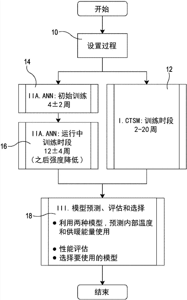
[0082] The embodiments of the present invention will now be described in the context of a building physical module (BPM) in a home environmental management system (HEMS) as a special case of a building environmental management system (BEMS).

[0083] The purpose of this particular BPM / system is to predict the temperature and heating demand of every room in the home in real time. More specifically, the home is divided into multiple thermal zones, each with its own sensor. The module will determine the temperature data and recommended heating requirements in each area, and provide control signals to achieve the recommended heating level.

[0084] In principle, the described model can be used to estimate the heat input required to reach a desired future state or the future state that a specific set of heat inputs will reach. In some embodiments, these two functions may be required for effective control optimization. Therefore, the BPM of some embodiments constitutes a device for ope...


PUM


Abstract

A method of operating an environment management system within a building, comprises using each of at least a first and a second model to predict, for a chosen time period ahead, one or both of: i) control requirements for the environment management system in light of a current measured system state and a desired future system state or ii) a future system state that would be reached with a particular set of control inputs; wherein the first model comprises a parameterised physical model of the building and the second model comprises an implicit model of the building. The predictions of the models are evaluated based on prior success at predicting the building's thermal behaviour for conditions similar to conditions that are forecast for the chosen time period ahead. A band of uncertainty for the desired or predicted future system state is determined. Based on the determined uncertainty bands, a control strategy that minimises a likely level of deviation from the desired future system state is selected. The control strategy comprises control parameters for the environment management system. The environment management system is operated to control the environment in the building in accordance with the selected control strategy.

Description

Technical field [0001] The present invention relates to a method and device for controlling an environmental management system in a building. Background technique [0002] Buildings are at least as diverse as humans. Although dwellings can be classified according to archetypes, there are at least hundreds of types. It is also clear that the many members of these prototype groups differ greatly from each other due to differences in construction details, post-modification and repair. Building systems, especially heating and ventilation systems, are also very different, and the interaction between these systems and the buildings in which they are located is complex. [0003] In addition, the energy behavior of the same building with different occupants can be very different. Enabling individuals to enter different occupants in different buildings can also lead to major behavior changes. Although it is clear that the behavior of the boiler is closely related to other components in ...

Claims


Application Information

Patent Timeline
Patent Type & Authority Applications(China)
IPC IPC(8): G05B17/02H04L12/28
CPCG05B17/02H04L12/2816G05B15/02G05B2219/2642Y02B70/30F24F11/62F24F11/30G05B19/418G05B23/0243G05B23/0283G06Q50/10G05B13/027G05B13/048
Inventor 安德鲁·迈克尔·哈斯莱特约翰·埃尔文·迈克尔·巴特比达伦·罗宾逊帕哈姆·A·米尔扎伊马津·阿拉瓦尼萨义德·贾布泊安娜·桑乔·托马斯
Owner ENERGY TECH INST
Why Eureka
Try Eureka