Air hammer device used for pulling hinge pin

An air hammer and pneumatic device technology, applied in metal processing equipment, metal processing, manufacturing tools, etc., can solve the problems of reducing work efficiency, complex work flow, and high labor costs, improving work efficiency, simplifying work flow, and connecting methods. Simple and convenient effects

Inactive Publication Date: 2017-12-08
湖北誉真科技有限公司
View PDF6 Cites 6 Cited by
  • Summary
  • Abstract
  • Description
  • Claims
  • Application Information

AI Technical Summary

Problems solved by technology

[0003] One is to manually use a sledgehammer to knock the end of the pin shaft. This method is labor-intensive, low in efficiency, and has a low success rate. It may take a long time to knock out the pin shaft.
[0004] Another way is to use a steel rod, the steel rod is strung with a heavy-duty ring hammer, the ring hammer can slide on the steel rod, the end of the steel rod is welded with a stop plate, the pin is welded to the front end of the steel rod, three The worker pulls the ring-shaped hammer and hits the stop plate at the other end of the steel rod to pull out the pin; this method is more efficient than the previous method and has a greater pulling force, but there is a problem of high labor costs. Three workers a day It may only be possible to pull out two pin shafts, and the existing pin shaft removal device adopts a welding method when connecting the pin shafts. The welding requires welding tools, and oxygen cutting and other methods are required to separate the pin shafts. The shaft is separated from the device for pulling out the pin, which makes the whole work process complicated and reduces work efficiency

Method used


Image

  • Air hammer device used for pulling hinge pin
  • Air hammer device used for pulling hinge pin
  • Air hammer device used for pulling hinge pin

Examples


Embodiment Construction

[0026] The present invention will be further described below in conjunction with the accompanying drawings and specific embodiments.

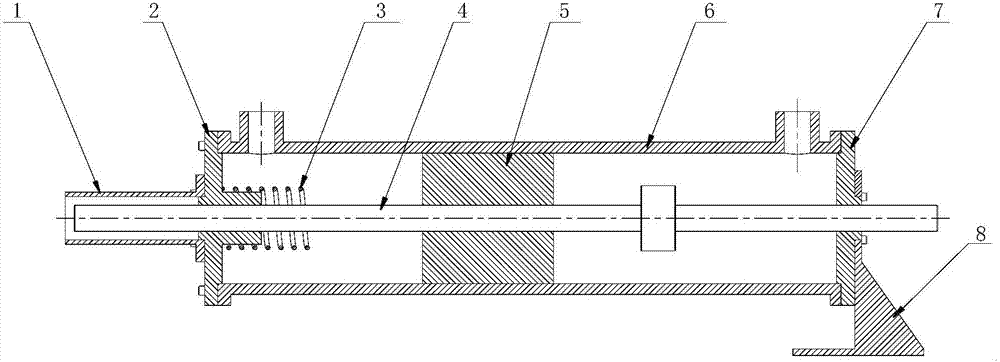
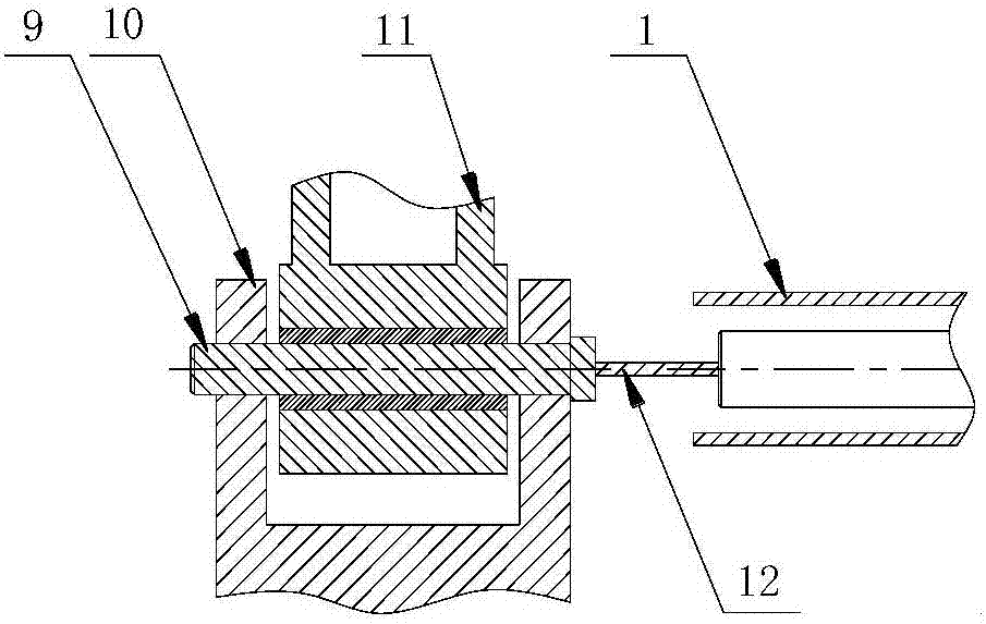
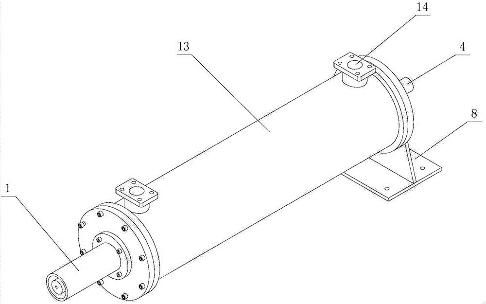
[0027] figure 1 , figure 2 , image 3 , Figure 4 It schematically shows the structure of an air hammer device for pulling out a pin shaft according to an embodiment of the present invention.

[0028] Such as figure 1 , figure 2 , image 3 , Figure 4 Shown, a kind of air hammer device for pulling pin shaft, it comprises the air hammer that is used to connect pin shaft, the pneumatic device that is used to drive air hammer movement, pin shaft and threaded rod; Described air hammer includes pin shaft The push-pull rod, the hammer that drives the pin shaft push-pull rod and the cylinder body with at least two air holes on the surface; the pneumatic device is connected to the air hammer through the air holes of the cylinder body; it is characterized in that: the pin shaft push-pull rod The end is provided with an internally threaded hole...


PUM


Abstract

The invention relates to an air hammer device used for pulling a hinge pin. The device comprises an air hammer used for being connected with the hinge pin, a pneumatic device used for driving the air hammer to move, the hinge pin and a threaded rod; the air hammer comprises a hinge pin push-pull rod, an iron hammer driving the hinge pin push-pull rod to move and a cylinder body with at least two air holes formed in the surface of the cylinder body; the pneumatic device is connected with the air hammer through the air holes of the cylinder body. The device is characterized in that an inner thread hole connected with the hinge pin is formed in the end portion of the hinge pin push-pull rod; an inner thread hole is formed in the central position of the end portion of the hinge pin; outer threads connected with the inner thread holes of the hinge pin push-pull rod and the hinge pin are arranged at both ends of the threaded rod respectively. According to the air hammer device, the threaded rod is connected with the hinge pin push-pull rod and the hinge pin respectively, and the connection means is simple and convenient, so that the situation that the hinge pin push-pull rod is connected with the hinge pin by means of welding is avoided, it is only necessary to rotate the threaded rod to separate the hinge pin push-pull rod from the hinge pin, thus the working efficiency is greatly improved, and the working process is simplified.

Description

technical field [0001] The invention relates to an air hammer device for pulling out pin shafts. Background technique [0002] The joints of the moving parts of construction machinery are connected by pin shafts. After long-term use, the grease channel inside the pin shaft is blocked, or the pin shaft is seriously worn, and the pin shaft needs to be replaced. There are currently two main methods of maintenance: [0003] One is to manually use a sledgehammer to knock the end of the pin shaft. This method is labor-intensive, low in efficiency, and has a low success rate. It may take a long time to knock out the pin shaft. [0004] Another way is to use a steel rod, the steel rod is strung with a heavy-duty ring hammer, the ring hammer can slide on the steel rod, the end of the steel rod is welded with a stop plate, the pin is welded to the front end of the steel rod, and three The worker pulls the ring-shaped hammer to knock on the stop plate at the other end of the steel ba...

Claims


Application Information

Patent Timeline
Patent Type & Authority Applications(China)
IPC IPC(8): B23P19/027
CPCB23P19/027
Inventor 曹泽鹏
Owner 湖北誉真科技有限公司
Why Eureka
Try Eureka