
scroll compressor

A scroll compressor and scroll technology, used in rotary piston machines, rotary piston engines, rotary piston pumps, etc., can solve problems such as reduced responsiveness, inability to respond properly, and a large number of parts , to achieve the effect of improving reliability

Active Publication Date: 2019-03-22
LG ELECTRONICS INC
View PDF5 Cites 0 Cited by
  • Summary
  • Abstract
  • Description
  • Claims
  • Application Information

AI Technical Summary

Problems solved by technology

[0019] However, the capacity variable device of the conventional scroll compressor as described above is composed of the adjusting ring 61, the pull ring 62, and the control valve 63, and the number of parts is large. In order to operate the adjusting ring 61, it is necessary to form a The first communication path 61a, the second communication path 61b, and the third communication path 61c have a problem that the structure of the adjustment ring 61 becomes complicated.
[0020] In addition, the capacity variable device of the conventional scroll compressor needs to use the refrigerant in the back pressure chamber 60a to quickly float the adjustment ring 61. However, since the adjustment ring 61 is formed in an annular shape and the control valve 63 is combined, the adjustment ring The added weight of the 61 makes it difficult to float the adjustment ring up quickly
In addition, the flow path for floating the adjustment ring 61 is long, and the refrigerant needs to flow into the space between the adjustment ring 61 and the pull ring 62 to float the adjustment ring 61, but there is still a back pressure chamber on the upper surface of the adjustment ring 61 60a pressure, so it is not easy to make the adjustment ring 61 float, so that the responsiveness of the valve is correspondingly reduced, and the capacity change of the compressor cannot be controlled quickly
[0021] In addition, the capacity variable device of the conventional scroll compressor cannot be equipped with a bypass hole and a check valve for opening and closing the bypass hole structurally. When overcompression occurs in the corresponding operation mode, it cannot be properly adjusted. countermeasures, thereby reducing the efficiency of the compressor

Method used


Image

  • scroll compressor
  • scroll compressor
  • scroll compressor

Examples


Embodiment Construction

[0066] Hereinafter, an embodiment of the scroll compressor of the present invention will be described in detail with reference to the drawings.

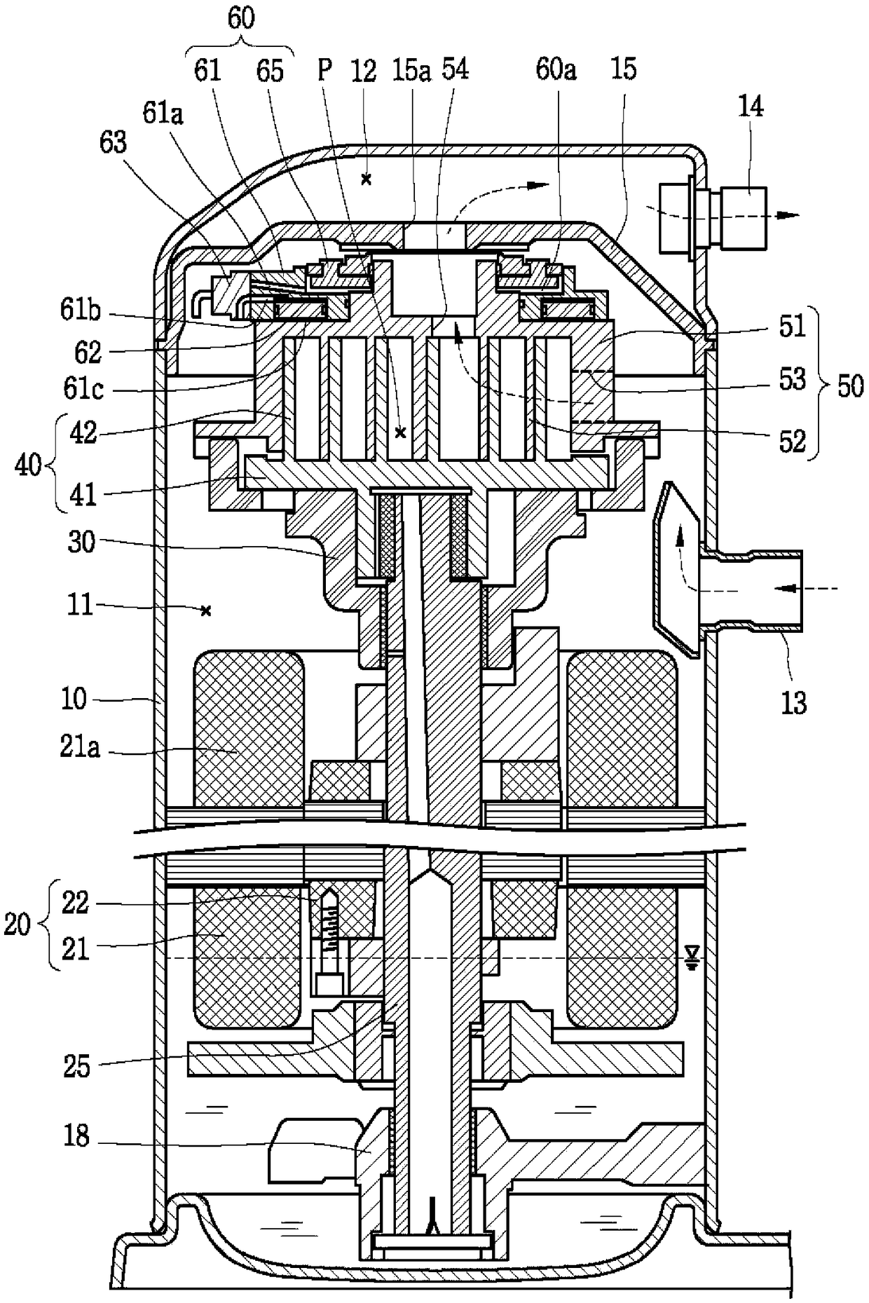
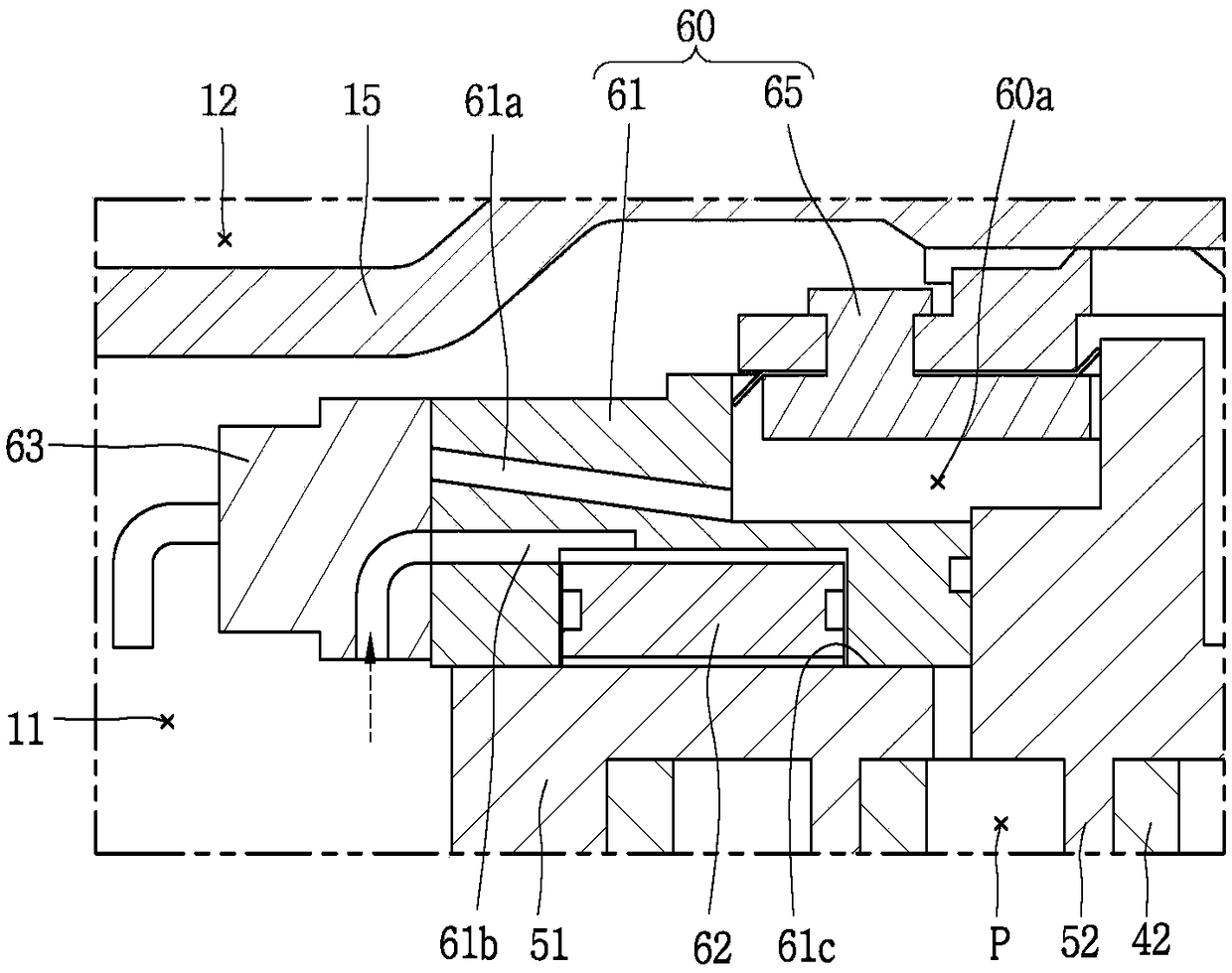
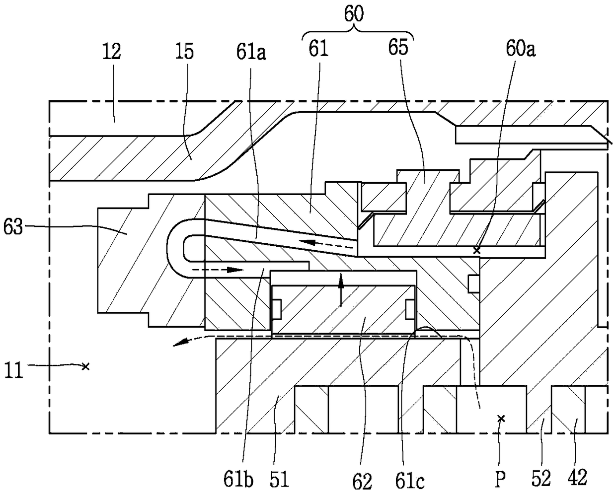
[0067] image 3 It is a longitudinal sectional view showing a scroll compressor having a capacity variable device of the present invention, Figure 4 is showing image 3 A perspective view of the interior of a scroll compressor with a variable capacity device, Figure 5 will be image 3 An exploded perspective view of the capacity variable device of an embodiment of Figure 6 will be Figure 5 A perspective view showing the assembled and cutaway capacity variable device of an embodiment of the present invention.

[0068] refer to image 3 The sealed internal space of the casing 110 of the scroll compressor of this embodiment is separated into a low-pressure part as a suction space by a high-pressure and low-pressure separation plate 115 provided on the upper side of a non-orbiting scroll 150 described later. 111 and a high pre...


PUM


Abstract

The scroll compressor of the present invention includes: a casing, a revolving member disposed inside the casing to perform revolving motion, and a non-revolving member forming a suction chamber, an intermediate pressure chamber, and a discharge chamber together with the revolving member. Comprising a compression chamber, a communication path that communicates the inside and outside of the compression chamber, and an on-off valve assembly that opens and closes the communication path, and is provided inside the casing outside the non-rotating member. , and, switch the valve assembly, make the on-off valve assembly operate, and set it inside the casing; thus, it is easy to manufacture, improves the responsiveness of the valve, eases the specification restriction on the valve, and sets the check valve Valves are used to prevent overcompression, and the assembly of the two valve assemblies is improved by placing the two valve assemblies on the outside of the non-rotating member.

Description

technical field [0001] The present invention relates to a scroll compressor, in particular to a capacity variable device of the scroll compressor. Background technique [0002] A scroll compressor is a compressor in which a non-orbiting scroll is provided in the inner space of a casing, and the orbiting scroll engages with the non-orbiting scroll to perform an orbiting motion, so that the non-orbiting scroll Two pairs of compression chambers consisting of a suction chamber, an intermediate pressure chamber, and a discharge chamber are formed between the non-orbiting scroll portion and the orbiting wrap portion of the orbiting scroll. [0003] The scroll compressor can obtain a relatively higher compression ratio than other types of compressors, so that the suction, compression, and discharge strokes of the refrigerant are gently connected, so that a stable torque (toque) can be obtained. The scroll compressor has such a Advantages, often used to compress refrigerants in air...

Claims


Application Information

Patent Timeline
Patent Type & Authority Patents(China)
IPC IPC(8): F04C18/02F04C29/00F04C29/12
CPCF04C18/02F04C29/00F04C29/126F04C2240/806F04C2240/80F04C23/008F04C18/0215F04C28/26F03C2/00F04C23/00F04C28/10F04C2240/30F04C2240/20F04C2240/40F04C2240/10F04C2210/26F04C28/18F04C29/0085F04C29/124
Inventor 陈弘均朱尚佑
Owner LG ELECTRONICS INC
Features
  • Generate Ideas
  • Intellectual Property
  • Life Sciences
  • Materials
  • Tech Scout
  • Unparalleled Data Quality
  • Higher Quality Content
  • 60% Fewer Hallucinations
Learn More