

Photographing device and method
A camera device and camera technology, which is applied in the field of photography, can solve the problems of limiting the field of view of the camera to take pictures, not being able to meet the shooting range of objects, and the range is small
- Summary
- Abstract
- Description
- Claims
- Application Information
AI Technical Summary
Problems solved by technology
Method used
Image

Examples
Embodiment 1
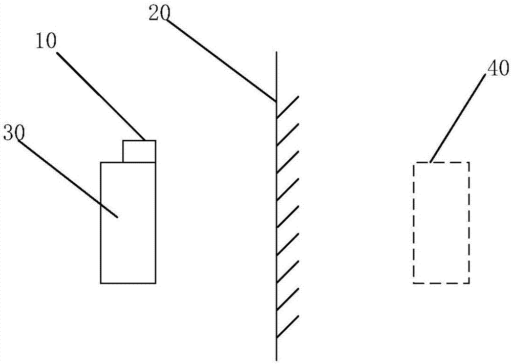
[0038] figure 1 It is a schematic diagram of an imaging device provided by Embodiment 1 of the present invention.
[0039] refer to figure 1 , the camera device provided by the embodiment of the present invention includes: a camera module 10, a reflection module 20, and a target object 30;
[0040] The camera module 10 is aligned with the reflective module 20 for photographing the target virtual image 40 formed after the target object 30 is reflected by the reflective module 20 .
[0041] Specifically, the distance from the object to be photographed to the focal plane of the lens of the camera module 10 is the object distance; Due to the small object distance, the shooting range is small, so that a complete image cannot be obtained. In an optical instrument, the lens of the optical instrument is taken as the apex, and the angle formed by the two edges of the maximum range where the object image of the object to be measured can pass through the lens is the angle of view; for...
Embodiment 2
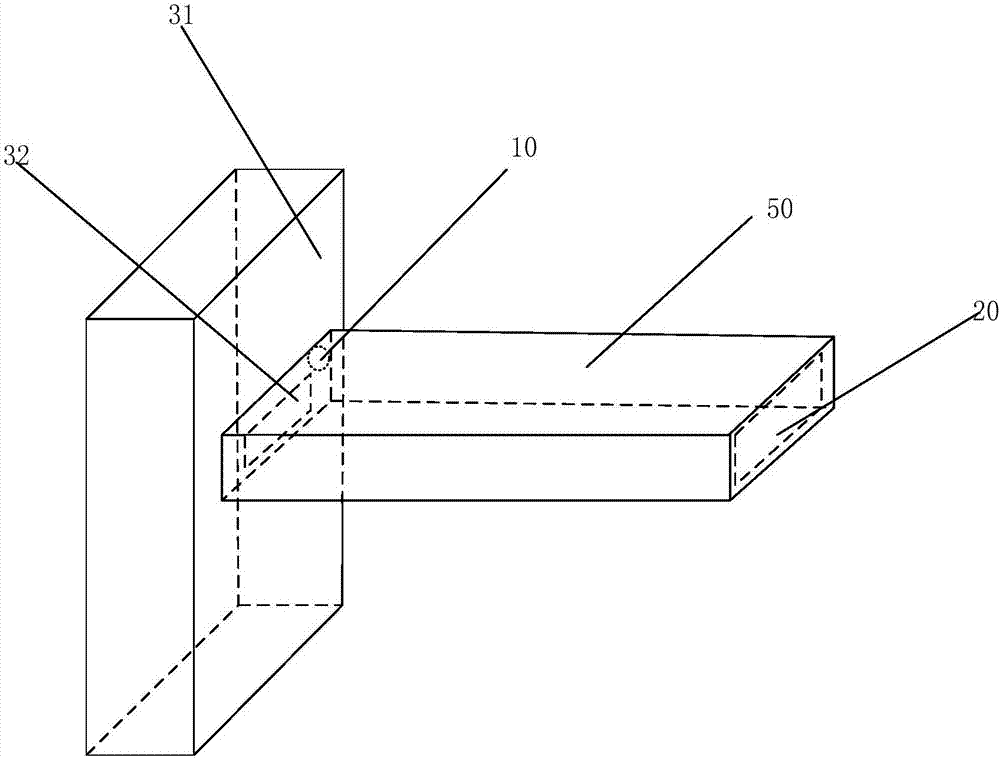
[0047] figure 2It is a schematic structural diagram of the imaging device provided by Embodiment 2 of the present invention.
[0048] Such as figure 2 As shown, the object 30 of the imaging device provided by the second embodiment of the present invention includes a watch 31 with a dial 32, the dial 32 is provided with a dial cover 50, and the dial cover 50 and the dial 32 form a closed channel; the dial cover 50 here It matches with the watch 31, that is, different types of watches 31 correspond to different types of dial covers 50, including the shape and size of the dial cover 50, etc.
[0049] The reflection module 20 is arranged on the side opposite to the dial in the airtight passage, and the camera module 10 is arranged on the same side as the dial in the airtight passage;
[0050] The camera module 10 is used to capture a virtual image of the dial formed after the dial is reflected by the reflection module 20 to obtain a photographed image.
[0051] Further, as ...
Embodiment 3
[0059] Figure 4 It is a flow chart of the imaging method provided by Embodiment 3 of the present invention.
[0060] refer to Figure 4 , Embodiment 3 of the present invention provides an imaging method, using the imaging device of Embodiment 1 above, the method includes:
[0061] Step S101, reflecting the target object through the reflection module to form a virtual image of the target;
[0062] Step S102, photographing the virtual image of the target to obtain a photographed image;
[0063] In step S103, the captured image is processed to obtain target data.
[0064] Specifically, by adding a reflective module that can be imaged, such as a flat mirror, on the opposite side of the object to be photographed, the camera is used to capture the virtual image in the mirror, so that the object distance is twice the distance from the object to the mirror. In addition, at a height determined In space, the maximum distance from the camera to the surface of the object to be photog...
PUM
 Abstract
Description
Claims
Application Information