

Image scanner
An image reading device and image technology, applied in the direction of image communication, electric recording technology using charge patterns, equipment using electric recording technology using charge patterns, etc., can solve the problems of large-scale optical systems, etc. Object distance, realize miniaturization, and increase the effect of depth of field
- Summary
- Abstract
- Description
- Claims
- Application Information
AI Technical Summary
Problems solved by technology
Method used
Image

Examples
Embodiment approach 1
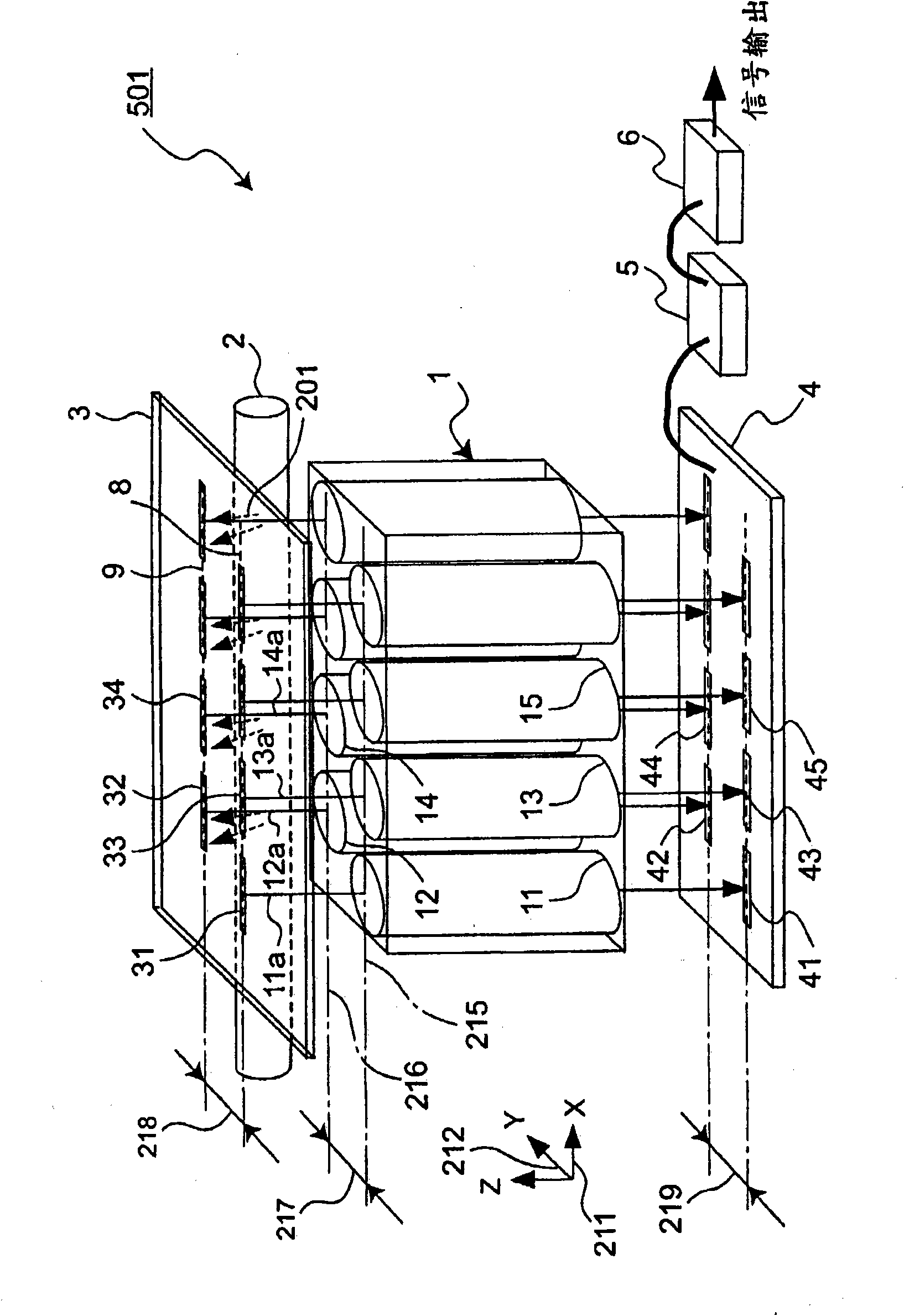
[0084] Next, use Figure 1 ~ Figure 3 An example of the image reading device according to Embodiment 1 of the present invention will be described.
[0085] The image reading device 501 according to the present embodiment includes an imaging optical system 1 , a light source 2 , imaging element units 41 , 42 , . Regarding these structural parts, the light source 2 is arranged near the original 7 as an example of the object to be read as an image, and the imaging optical system 1 is arranged so that the light reflected by the original 7 can be incident. The imaging device section 41 and the like are arranged. Such an image reading device 501 reads the image of the original document 7 along the main scanning direction (X direction) 211, and also scans the original document 7 in the sub scanning direction (Y direction) 212 perpendicular to the main scanning direction 211, and reads the original document. All images in 7. In addition, the manuscript 7 refers to an object to be r...
Embodiment approach 2
[0136] refer to Figure 9 ~ Figure 12 An example of the image reading device 502 in Embodiment 2 of the present invention will be described.
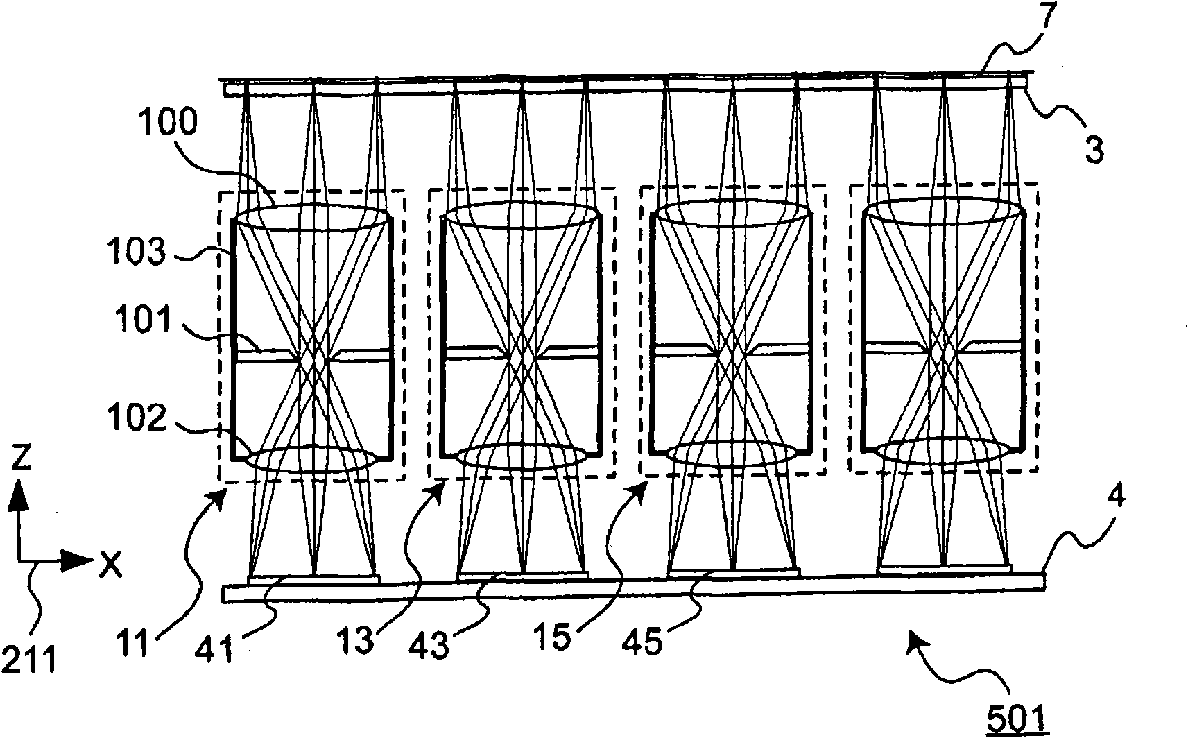
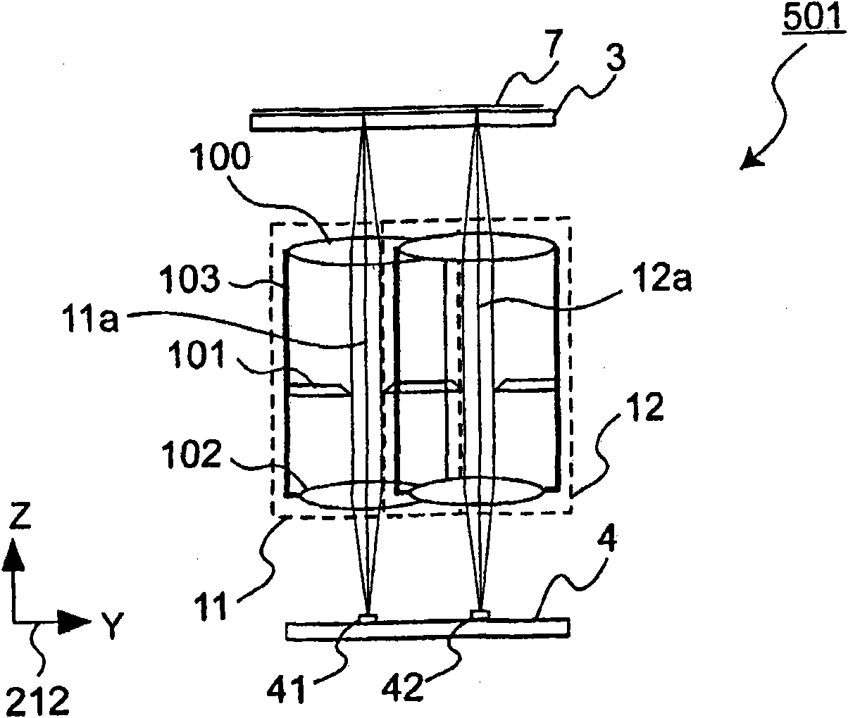
[0137] In the image reading device 501 according to Embodiment 1, the slave originals among the chief rays in the cells 11, 13, . . . belonging to the first row 215 and in the cells 12, 14, . 7 The rays towards the units 11, 13, ... and the units 12, 14, ... are as figure 2 are shown parallel to each other, and between cells 11, 13, ... and cells 12, 14, ... in the first column 215 and the second column 216, as image 3 The rays directed from the document 7 to the individual units within the shown chief rays are also parallel. In addition, in an example of the present embodiment, since the optical axis is a straight line, words such as light rays from the original document 7 toward each unit among the chief rays can be replaced with words such as the optical axis.
[0138] In contrast, image reading device 502 in Embodiment 2 has a ...
Embodiment approach 3
[0146] refer to Figure 13 An example of the image reading device 503 in Embodiment 3 of the present invention will be described.
[0147] In the first and second embodiments described above, the light rays 11a, 12a, . Alternatively, the units 11, 12, . . . are arranged in a slightly inclined manner. On the other hand, in the image reading device 503 according to Embodiment 3, each light ray behind the bending mirror 111, 112 among the chief light rays of each unit 11, 12, . . . In a parallel manner, the units 11, 12, . . . are arranged.
[0148] That is, in the image reading device 503 in the third embodiment, scattered light from the original document 7 that is incident on the units 11, 12, ... is provided between the original document 7 and the units 11, 12, ... The optical path is bent by bending mirrors 111, 112. In this embodiment, the first bending mirror 111 is provided corresponding to the optical axes 11a, 13a, . . . in the units 11, 13, . . . The optical axes 1...
PUM
 Abstract
Description
Claims
Application Information