Light field display system

A display system and light field technology, applied in the field of 3D display, can solve the problems of large viewing angle range, large imaging equipment volume, difficult to realize graphic lighting and display, etc., and achieve the effect of increasing viewing angle range, improving resolution and depth of field

Active Publication Date: 2019-09-20
FAITH BILLION TECH DEV LTD
View PDF5 Cites 13 Cited by
  • Summary
  • Abstract
  • Description
  • Claims
  • Application Information

AI Technical Summary

Problems solved by technology

However, the more viewpoints, the larger the resources occupied and the lower the resolution, and the conflict between vergence adjustment and focus adjustment (VAC effect) is more obvious
In addition, the program production of multi-viewpoint 3D display, whether it is animation or video, faces the problems of high technical difficulty and high cost, so its application range is limited
Stereoscopic display technology uses rotating screens or multiple screens evenly distributed in space to realize sequential lighting of pixels at different times and different spatial positions. Due to the persistence of vision effect of the human eye, 3D images can be perceived, but the spatial resolution of the stereoscopic image screen of this technology Insufficient rate, limited range of application
Directional backlight technology is to process a specially designed structure on the light guide plate, so that the light propagates in different directions to form parallax lighting. This technology relies on LCD screens and directional backlights, which are difficult to achieve large-format graphic lighting and display. VAC effect is serious
Multi-layer display technology is a light field display technology with a spatial plane viewing angle. Its basic principle is to display different video images in different display screens by arranging more than two display screens in one display screen. These images have a certain depth. Information, after processing these images one by one, and then through the composite effect of multiple display screens, a three-dimensional display can be achieved, but the imaging equipment for realizing multi-layer display is too large, the brightness becomes low, and the cost is high and it is difficult to realize
Integrated imaging is a naked-eye 3D stereoscopic display technology that uses lens arrays to record and reproduce real 3D scenes according to the reversible principle of light. However, in this method, the imaging image point position is single and the depth of field is small.
Holographic three-dimensional display technology uses two beams of coherent light, one of which is reflected by the surface of a real object and carries the intensity and phase information of the object surface, and the other beam does not carry any information. The two beams of light interfere with each other to form a complex holographic light field , this holographic light field contains information such as the brightness and darkness of the object surface, depth of field, etc., so as to reproduce the information of the light field, record and reproduce the intensity and phase of light, and provide all the depth perception information required by the human visual system to realize It allows many people to watch the same 3D image at the same time, and breaks the limitation of naked-eye 3D technology on the number of viewers. However, the viewing angle of holographic 3D display technology is very small, and the scope of application is limited.
[0004] To sum up, among the existing naked-eye 3D display technologies, each method cannot simultaneously have the advantages of large depth of field, no VAC effect, obvious moving parallax, large viewing angle range, high brightness, and can support multiple people to watch at the same time.

Method used


Image

  • Light field display system
  • Light field display system
  • Light field display system

Examples


Embodiment

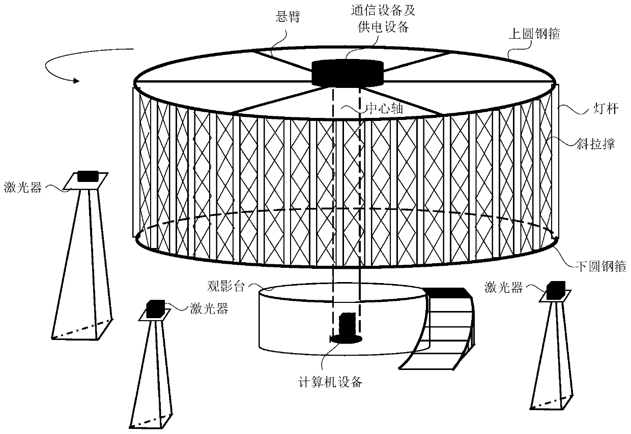
[0046] figure 1 It is a schematic structural diagram of a light field display system provided by an embodiment of the present invention, and this embodiment is applicable to realize naked-eye 3D image display. Such as figure 1 As shown, the structure of the light field display system specifically includes:

[0047] Rotating display subsystem, display positioning device, human eye tracking subsystem, communication subsystem and computer equipment.

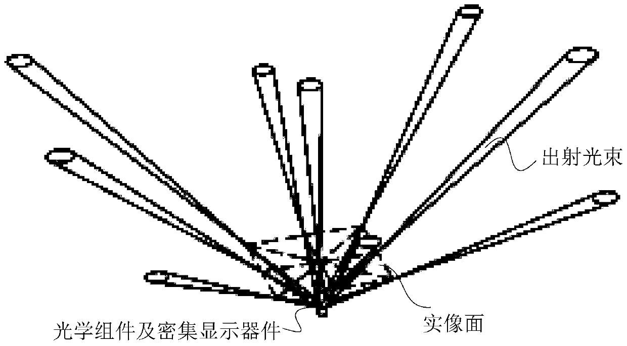
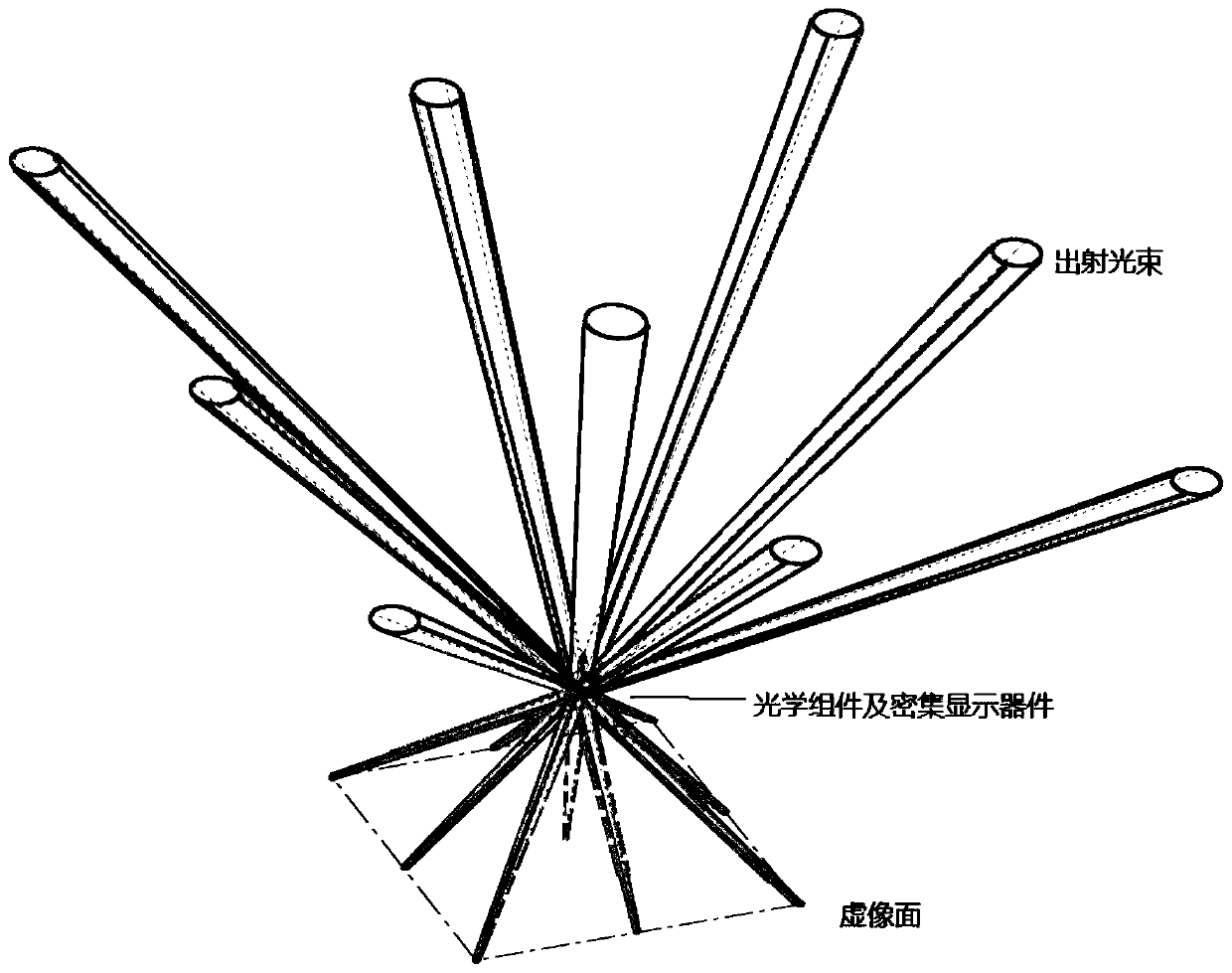
[0048] Among them, the rotating display subsystem is a rotating structure built by a light pole, a controller, a light pole fixing device, and a motor. The light pole includes a first preset number of light boards, and each light board includes vector pixels An array and a vector pixel driving circuit, the vector pixel array includes real image vector pixels and virtual image vector pixels.

[0049] Specifically, each vector pixel in the vector pixel array is a light source formed by integrating and packaging dense light emitting...


PUM


Abstract

The embodiment of the invention discloses a light field display system, which comprises a rotating display screen subsystem, a display screen positioning device, a human eye tracking subsystem and a computer. The rotating display screen subsystem comprises a lamp pole which comprises a lamp panel, and the lamp panel comprises a vector pixel array which comprises real image vector pixels and virtual image vector pixels; the display screen positioning device comprises a plurality of lasers and light-sensitive sensors; the human eye tracking subsystem comprises a human eye tracking camera and a position computing unit, and computer equipment is connected with the rotating display screen subsystem and the human eye tracking subsystem; and a lamp panel controller is used for determining the position of the lamp panel according to sensing data of the display screen positioning device, and all the vector pixels on the lamp panel are driven to display the display content in the display direction so as to achieve 3D image display. Multiple people can simultaneously watch a naked eye 3D image, audience at different watching positions watch the different content of the 3D image, and the resolution and the field depth of the naked eye 3D image are increased.

Description

technical field [0001] Embodiments of the present invention relate to 3D display technologies, and in particular to a light field display system. Background technique [0002] Naked-eye 3D technology allows users to get rid of the shackles of 3D glasses and directly observe 3D images with naked eyes. At present, with the development of display technology, naked-eye 3D display technology mainly includes multi-viewpoint display technology, volumetric display technology, directional backlight display technology, integrated imaging display technology, multi-layer display technology and holographic 3D display technology. [0003] Among them, the emergence of multi-viewpoint display technology is due to the fact that the viewing angles of every two viewpoints are too small, so the method of increasing the number of viewpoints is used to solve the problem of too small viewing angles. However, the more viewpoints, the larger the resources occupied and the lower the resolution, and ...

Claims


Application Information

Patent Timeline
Patent Type & Authority Applications(China)
IPC IPC(8): G09F9/37G09F9/302G09G3/00G02B27/22G02B27/00H04N13/302H04N13/383
CPCG09F9/37G09F9/302G09G3/005G02B27/0093H04N13/302H04N13/383G02B30/00G09F19/12G09G3/008G09G2300/0426G02B30/54
Inventor 卢增祥
Owner FAITH BILLION TECH DEV LTD
Why Eureka
Try Eureka