Multiscale optical system having dynamic camera settings

a dynamic camera and multi-scale technology, applied in the field of optics, can solve the problems of large lenses, exacerbated problems, and insufficient camera capture of the diversity of a complex scen

Active Publication Date: 2016-08-30
DUKE UNIV
View PDF64 Cites 10 Cited by
  • Summary
  • Abstract
  • Description
  • Claims
  • Application Information

AI Technical Summary

Benefits of technology

[0009]The present invention enables simultaneous imaging of a scene having features at diverse ranges. Embodiments of the present invention include a single objective lens and an arrangement of individually controllable microcameras that image the scene through the objective lens. Embodiments of the present invention enable imaging of large-area scenes with high resolution, scenes having a large range of illumination intensity, and scenes having large depth-of-field. Embodiments of the present invention are particularly well suited for applications such as aerial surveillance, panoramic imaging, and imaging of sporting events.
[0012]The focus of each microcamera determines the position within the image field (along the optical axis of that camera) of the image region that is focused onto its respective focal-plane array. As a result, by focusing different microcameras at different distances within the thickness of the three-dimensional image field, different ranges of the scene can be simultaneously imaged. Further, by varying the positions of the focus regions, an arbitrarily shaped surface may be approximated by the union of the focus regions of the microcameras. Embodiments of the present invention, therefore, enable composite images of the scene that can have enhanced depth-of-field. This affords embodiments of the present invention significant advantages over conventional single-aperture cameras, which have a single focal surface that must be varied globally over the entire object, which requires that the available imaging volume is confined to this single uniform surface.
[0013]Likewise, embodiments of the present invention have advantages over conventional camera arrays. Embodiments of the present invention can achieve higher spatial resolution than arrays of conventional cameras because the objective lens effectively magnifies the entrance pupil of each microcamera. As a result, each microcamera is the equivalent of a telescope, but in which the equivalent resolution of an array of larger telescopes is realized with a smaller and more economical imaging system.
[0014]Because each microcamera has controllable focus, exposure, gain, and dynamic range, multiple measurements of the imaging system can be acquired, with the microcameras assuming various configurations of these parameters. The results of these multiple measurements can then be synthesized into a single composite image which may contain enhanced depth-of-field, dynamic range, or contain three-dimensional or parallax views.
[0019]In some embodiments, one or more of the microcameras has a controllable stop size, which enables different cameras to have different depths-of-field. As a result, features of interest within a particular microcamera can be sampled while maintaining a desired level of illumination and spatial resolution.

Problems solved by technology

Unfortunately, a conventional single-aperture camera only allows one fixed shutter speed, focus position, aperture size, color balance, and polarization per image.
As a result, such a camera can not sufficiently capture the diversity of a complex scene, as described above, because typically there is no single combination of aperture stop size, exposure time, focus position, color balancing, and zoom position that can capture the desired level of detail in the scene.
This problem is exacerbated when the scene includes a wide area, such as a sporting event, a natural landscape, or even a large room.
Although such a multi-camera system overcomes many of the disadvantages inherent to the single-aperture camera, the size of the entrance pupil of each camera in the array must be sufficiently large to resolve features in the scene of interest.
Multi-camera imaging systems, therefore, require relatively large lenses and, as a result, tend to be large and bulky.
Further, their bulk often gives rise to dead zones in the composite image due to a limit on how close the cameras can be placed to one another.

Method used


Image

  • Multiscale optical system having dynamic camera settings
  • Multiscale optical system having dynamic camera settings
  • Multiscale optical system having dynamic camera settings

Examples


Embodiment Construction

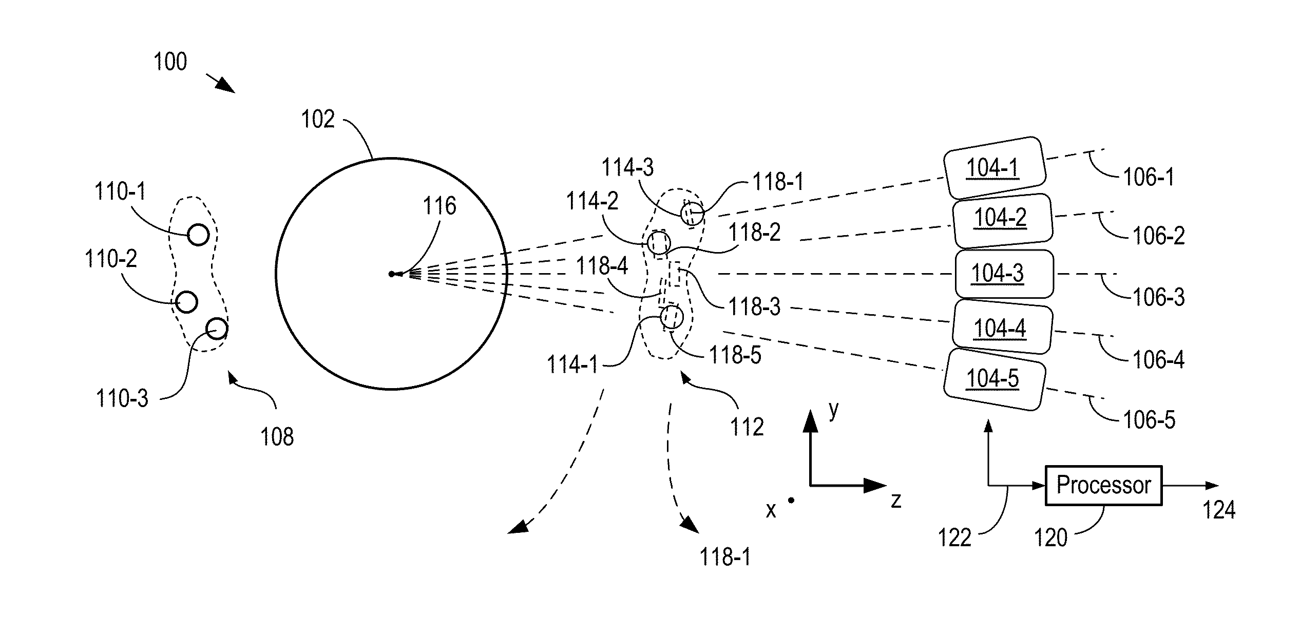
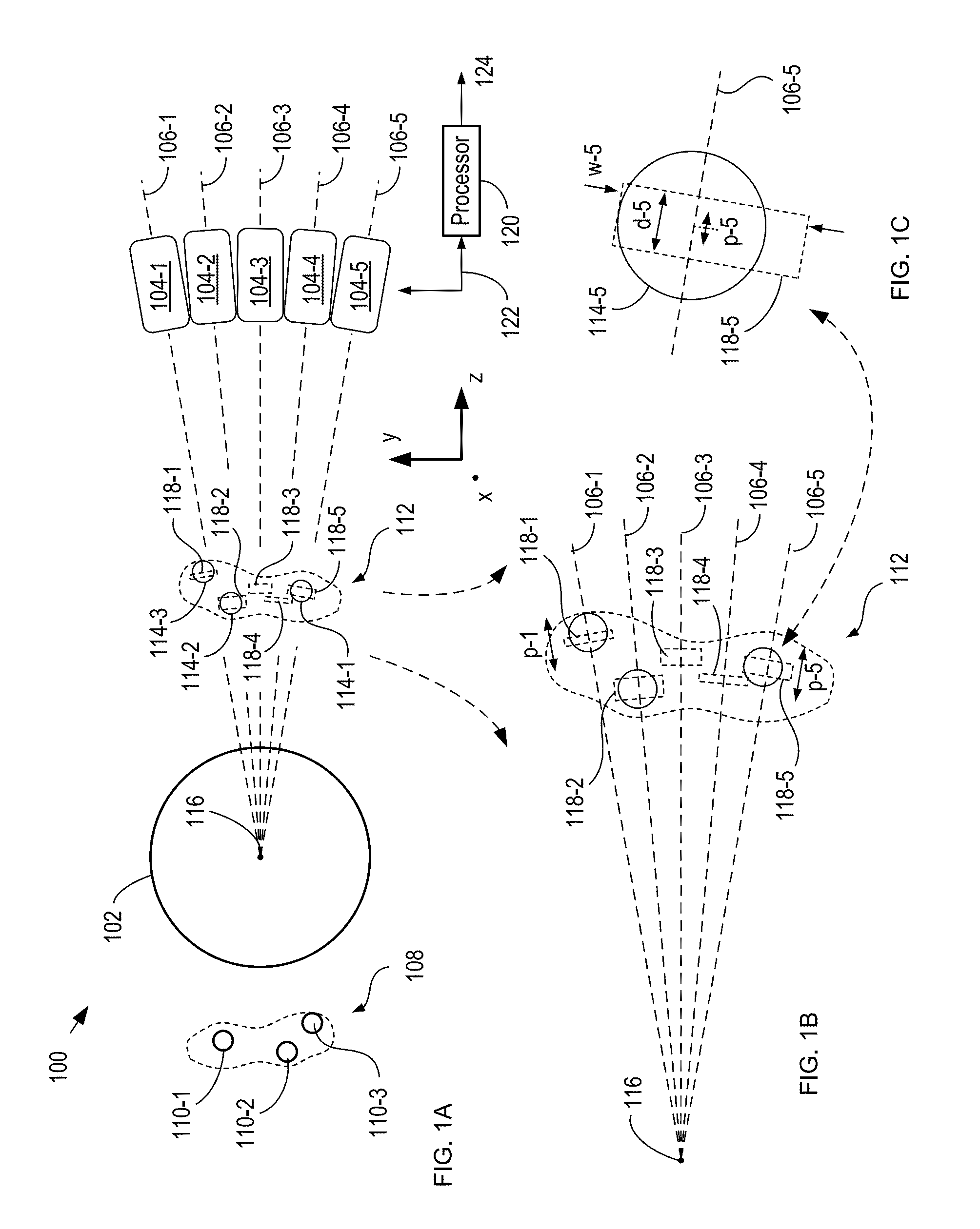
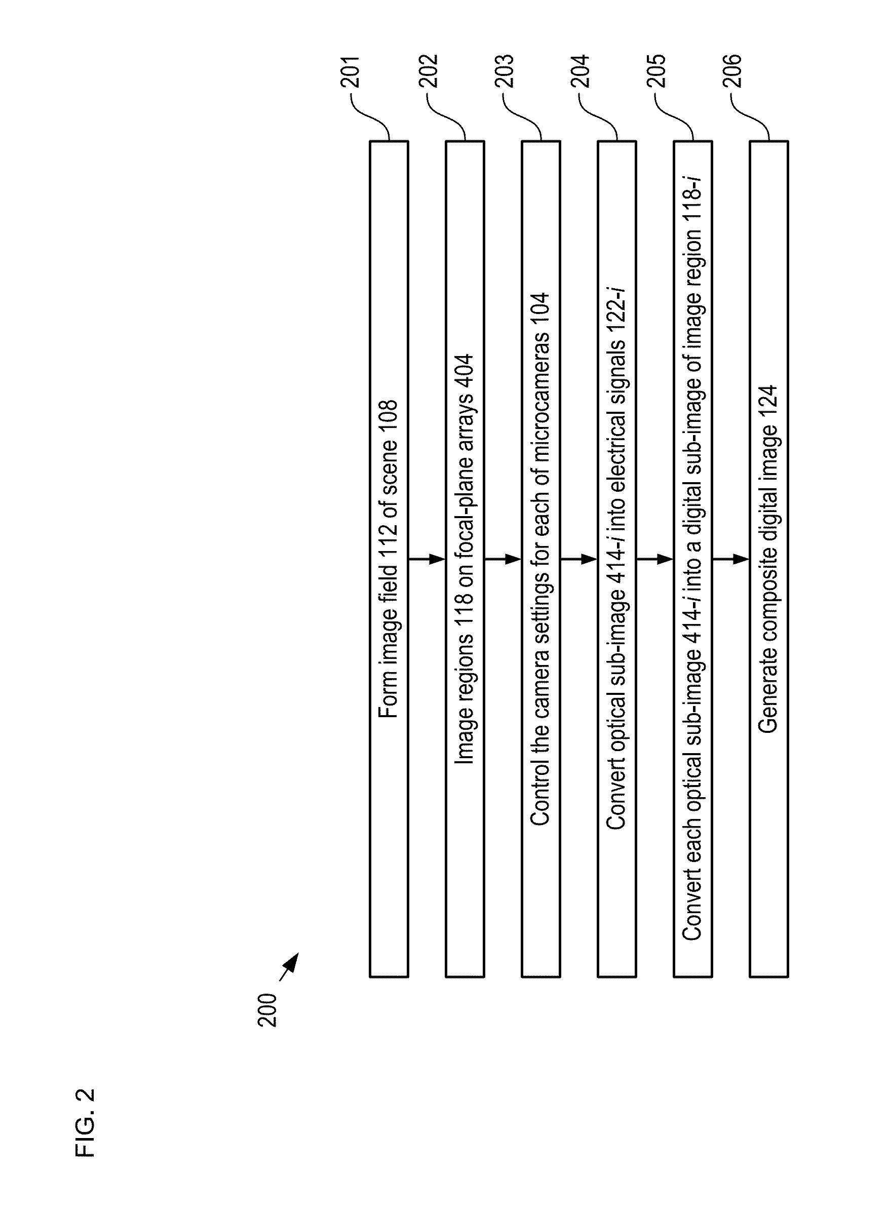
[0034]This application claims priority of parent cases: U.S. patent application Ser. No. 13 / 095,407, which is a continuation-in-part of U.S. patent application Ser. No. 12 / 651,894 (now U.S. Pat. No. 8,259,212. As disclosed in the parent cases, a multiscale optical system comprises a single objective lens (which can be either a monocentric lens or a non-monocentric lens) and an array of microcameras, each of which includes a microcamera (e.g., one or more lenses) and a focal-plane array. The objective lens and the microcameras collectively image a scene onto the plurality of focal-plane arrays as a plurality of optical sub-images. Each microcamera has a unique optical axis and images a different image region of the scene through the objective lens to produce a different one of the optical sub-images. The sensor arrays convert the plurality of optical sub-images into digital representations (i.e., digital images) of portions of the scene that can then be combined to form a composite d...


PUM


Abstract

A multiscale imaging system including microcameras having controllable focus, dynamic range, exposure, and magnification is disclosed. The objective lens forms a three-dimensional image field of a scene. Image regions of the image field are relayed by the microcameras onto their respective focal-plane arrays, which collectively provide a plurality of digital sub-images of the scene. The digital sub-images can then be used to form a composite digital image of the scene that can have enhanced depth-of-field, enhanced dynamic range, parallax views of the scene, or three-dimensionality.

Description

CROSS REFERENCE TO RELATED APPLICATIONS[0001]This case is a continuation-in-part of co-pending U.S. patent application Ser. No. 13 / 095,407 filed Apr. 27, 2011, which is a continuation-in-part of U.S. patent application Ser. No. 12 / 651,894 (now U.S. Pat. No. 8,259,212), filed 4 Jan. 2010 , which claims priority of U.S. Provisional Patent Application 61 / 142,499, filed Jan. 5, 2009, each of which is incorporated herein by reference in its entirety.STATEMENT REGARDING FEDERALLY SPONSORED RESEARCH[0002]This invention was made with Government support under Grant Number HR0011-10-C-0073 awarded by the Defense Advanced Research Projects Agency (DARPA). The Government has certain rights in the invention.FIELD OF THE INVENTION[0003]The present invention relates to optics in general, and, more particularly, to imaging systems.BACKGROUND OF THE INVENTION[0004]A complex scene includes objects or portions of the scene that are at a wide variety of distances from the camera. In some cases, the sce...

Claims


Application Information

Patent Timeline
Patent Type & Authority Patents(United States)
IPC IPC(8): H04N5/262G02B13/06H04N5/225H04N5/232H04N13/02G02B27/00G03B37/04
CPCG02B13/06H04N5/2254H04N5/2624H04N13/0203H04N5/23212H04N5/23238G02B27/0025G03B37/04H04N13/204H04N23/55H04N23/67H04N23/698
Inventor BRADY, DAVID JONESKIM, JUNGSANGMARKS, DANIELSON, HUI SEONG
Owner DUKE UNIV
Why Eureka
Try Eureka