Oil pressure ankle joint

An ankle joint, hydraulic technology, applied in the direction of ankle joint, joint implants, joint implants, etc., can solve the problems of difficult maintenance, inconvenient use, complex internal components of the structure, etc.

Inactive Publication Date: 2017-12-12
KEN DALL ENTERPRISE
View PDF8 Cites 0 Cited by
  • Summary
  • Abstract
  • Description
  • Claims
  • Application Information

AI Technical Summary

Problems solved by technology

[0005] However, the above-mentioned ankle joint decompression adjustment mechanism has relatively complex internal components, which is not easy for subsequent maintenance and overhaul. When used in a magnetic environment, whether it will interfere with the design of the magnetic valve port has safety concerns; and When the internal hydraulic fluid stock is not enough for lubrication, it needs to be replenished through the oil hole, which is not very convenient in actual use
Therefore, the problems of complex structure and inconvenient use need to be improved urgently

Method used


Image

  • Oil pressure ankle joint
  • Oil pressure ankle joint
  • Oil pressure ankle joint

Examples


Embodiment Construction

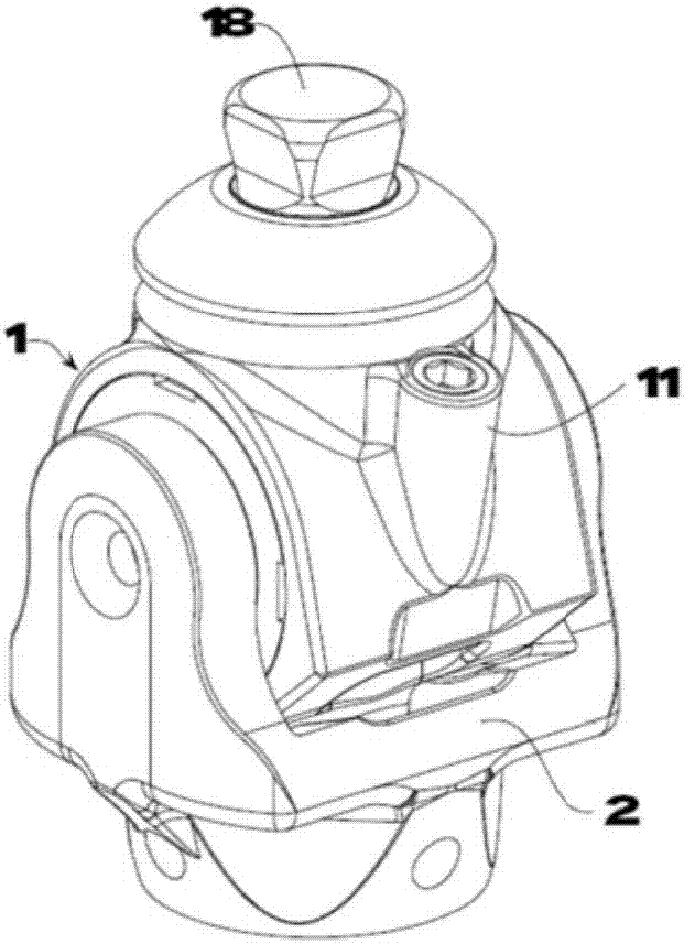
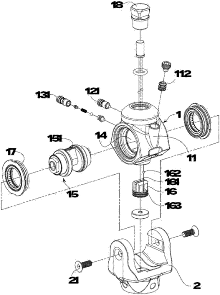
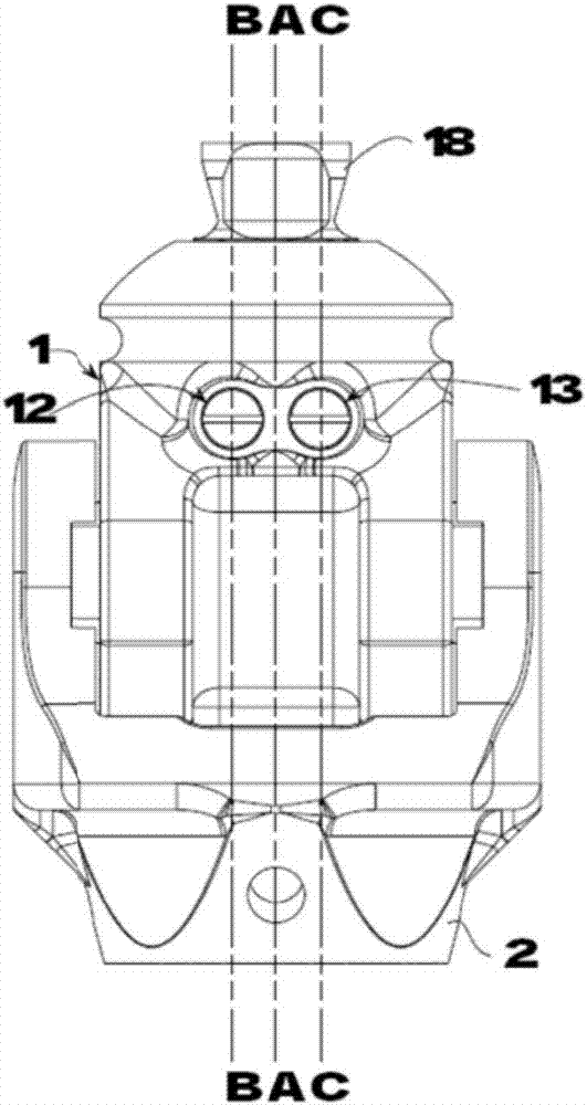
[0028] Generally according to the present invention, the best available embodiment, and cooperating Figure 1 to Figure 7 After being described in detail, the understanding of the present invention can be increased. The present invention is a kind of hydraulic ankle joint, which has an ankle hydraulic cylinder 1 in its structure, and a bearing 18 is provided on the top to connect other prosthetic parts, and the bottom is a Equipped with a prosthetic foot 3 for use, the foot and ankle hydraulic cylinder 1 has an oil replenishment chamber 11, a first pressure regulating chamber PF12, a second pressure regulating chamber DF13, and a housing connected to the above-mentioned chambers. space 14, the oil supply chamber 11 is set on one side of the ankle hydraulic cylinder 1, and the first pressure regulating chamber PF12 and the second pressure regulating chamber DF13 are set on the other side of the ankle hydraulic cylinder 1, in coordination with image 3 As shown by the section li...


PUM


Abstract

The invention provides an oil pressure ankle joint. The oil pressure ankle joint comprises an ankle hydraulic cylinder, wherein the ankle hydraulic cylinder comprises an oil supplementing chamber, a first pressure adjusting chamber PF, a second pressure adjusting chamber DF, and accommodating space communicating with each chamber, the accommodating space allows for pivoting of an oil pressure shaft core in match with a locating piece, set screws are matched at two sides of the oil pressure shaft core for screwing, and the ankle hydraulic cylinder is pivoted in a pivoting base and can carry out rotation swing movement relative to the pivoting base; an extending part is arranged in the middle of the oil pressure shaft core, an oil baffle block is arranged below the oil pressure shaft core, so that a front chamber and a rear chamber which communicate with each other and allow fluid to flow inside are formed through the separation by the oil pressure shaft core, meanwhile, the first pressure adjusting chamber PF and the second pressure adjusting chamber DF can be used for correspondingly adjusting the pressure of fluid in the front chamber and the rear chamber, so that the impact force born by a user during walking is effectively alleviated, the walking posture is natural and easy, in addition, the oil supplementing chamber can automatically supplement fluid by utilizing the differences of oil pressure, and thus the maintenance times of the user can be reduced.

Description

technical field [0001] The present invention is a kind of hydraulic ankle joint, through which the shaft center of the hydraulic pressure is rotated to match the channel, so that the pressure can be adjusted according to the user's walking speed, so that the impact force when landing on the ground can be effectively slowed down, and the walking posture is more relaxed and natural. Background technique [0002] With the advancement of medicine in medical practice and technology, the design of prosthetic joints also ranges from the application of basic cushioning materials to the combined use of air pressure and oil pressure through structural improvement to improve shock absorption and natural movement. However, there is still much room for improvement in current applications. [0003] The commonly used knee joint mainly uses a variety of connecting rod structures to allow users to more realistically simulate the normal knee movement. However, most of the other components con...

Claims


Application Information

Patent Timeline
Patent Type & Authority Applications(China)
IPC IPC(8): A61F2/42
CPCA61F2/30721A61F2/4202A61F2002/30329A61F2002/30537A61F2002/30621A61F2002/30639A61F2002/30649A61F2002/30673
Inventor 郑嘉宝吴复国吴祥铭
Owner KEN DALL ENTERPRISE
Why Eureka
Try Eureka