Dynamic knee joint with combined active movement and passive movement

A knee joint and combined technology, applied in the direction of artificial legs, etc., can solve problems such as unnatural gait, loud noise, and large size, and achieve the effect of improving walking efficiency and energy efficiency

Active Publication Date: 2012-08-22
PEKING UNIV
View PDF4 Cites 0 Cited by
  • Summary
  • Abstract
  • Description
  • Claims
  • Application Information

AI Technical Summary

Problems solved by technology

Artificial muscle knee joints, pneumatically driven knee joints and hydraulically driven knee joints can provide sufficient power, but are too bulky, too noisy, and have low control precision
Motor-driven knee joints are directly driven by motors. Although such a knee joint can precisely control the angle of the knee joint, the knee joint needs motor control all the time, and the gait is unnatural.
And because it cannot make full use of the kinetic energy and inertia when people walk, so the efficiency is very low

Method used


Image

  • Dynamic knee joint with combined active movement and passive movement
  • Dynamic knee joint with combined active movement and passive movement
  • Dynamic knee joint with combined active movement and passive movement

Examples


Embodiment Construction

[0018] The present invention will be described in detail below in conjunction with the accompanying drawings and embodiments.

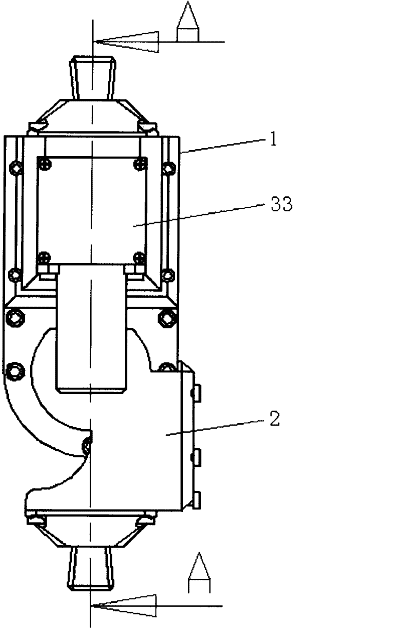
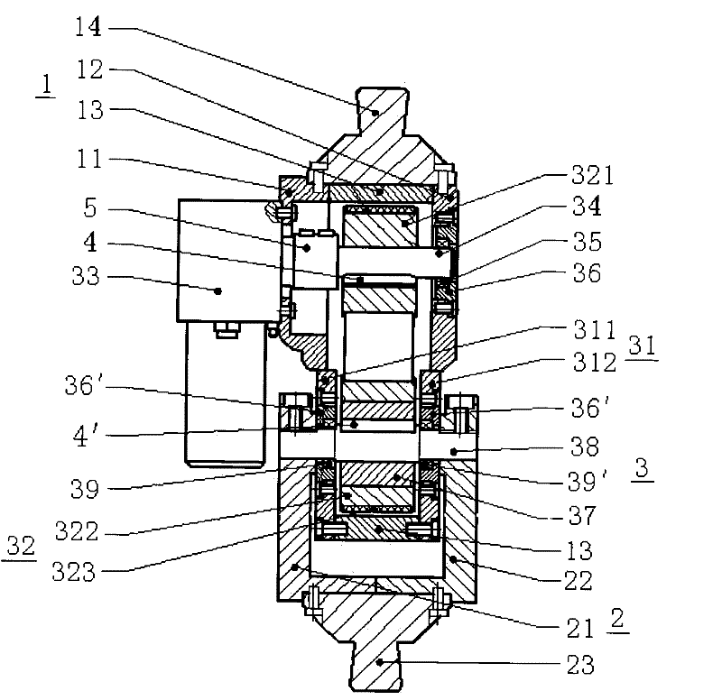
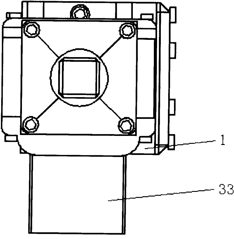
[0019] like Figure 1 ~ Figure 3 As shown, the present invention includes a large leg connecting frame 1, a small leg connecting frame 2 and a knee joint movement mechanism 3. Thigh connecting frame 1 comprises the thigh left baffle plate 11, the thigh right baffle plate 12 and the thigh middle baffle plate 13 which are fixedly connected together by bolts, and the tops of the thigh left baffle plate 11 and the thigh right baffle plate 12 are fixedly connected by bolts to receive the thigh Cavity connecting head 14, thigh receiving cavity connecting head 14 is fixedly connected with a receiving cavity (not shown in the figure), and receiving cavity is fixedly connected with the thigh stump of the disabled.

[0020] The shank connecting frame 2 comprises a shank left baffle plate 21 and a shank right baffle plate 22 fixedly connected together by bolts,...


PUM


Abstract

The invention relates to a dynamic knee joint with combined active movement and passive movement. The dynamic knee joint is characterized by comprising a thigh connecting rack, a shank connecting rack and a knee joint moving mechanism, wherein the knee joint moving mechanism comprises a knee joint connecting rack, a synchronous pulley connecting mechanism and a motor; the motor is fixedly connected with the thigh connecting rack and an output end of the motor is connected with one end of a driving shaft through a coupling; the other end of the driving shaft is fixedly connected with the thighconnecting rack through a driving shaft bearing; a knee joint shaft is fixedly supported on the knee joint connecting rack through a knee joint bearing; the two ends of the knee joint shaft are fixedly connected with the shank connecting rack; the knee joint shaft is fixedly connected with an inner ring of a one-way clutch through a knee joint shaft connecting key; and an outer ring of the one-way clutch is connected with the driving shaft through the synchronous pulley connecting mechanism. The dynamic knee joint is widely applied to the research of a flexible dynamic joint of an artificial limb and can serve the disabled.

Description

technical field [0001] The invention relates to the technical field of intelligent bionic machinery, in particular to a dynamic knee joint that can not only provide power but also fully utilize the active and passive movements of kinetic energy and inertia when people walk. Background technique [0002] Every year, tens of thousands of people with lower limb amputations are caused by various natural disasters, diseases and traffic accidents, a large part of which are thigh amputee patients. These thigh amputee patients have lost their ability to work due to the loss of their lower limbs, and even cannot take care of themselves. In order to restore their ability to work and improve their quality of life, they are in urgent need of artificial limbs. [0003] The knee joint is the most important part of the thigh prosthesis, because the knee joint directly affects the daily activities (such as walking, going up and down stairs), the efficiency of movement and the naturalness o...

Claims


Application Information

Patent Timeline
Patent Type & Authority Patents(China)
IPC IPC(8): A61F2/64
Inventor 朱金营王启宁袁克彬王龙
Owner PEKING UNIV
Why Eureka
Try Eureka