Multi-shaft hydraulic knee joint

A knee joint and hydraulic technology, applied in the field of bionic devices, can solve the problems of unnatural gait, poor movement stability and safety, complex knee joint structure, etc. Effect

Pending Publication Date: 2020-12-08
北京市康复辅具技术中心
View PDF0 Cites 0 Cited by
  • Summary
  • Abstract
  • Description
  • Claims
  • Application Information

AI Technical Summary

Problems solved by technology

[0004] The purpose of the present invention is to provide a multi-axis hydraulic knee joint, which aims to solve the problems of complex structure of the existing knee joint, large space occupation, unnatural gait of the prosthesis wearer, and poor movement stability and safety. question

Method used


Image

  • Multi-shaft hydraulic knee joint
  • Multi-shaft hydraulic knee joint
  • Multi-shaft hydraulic knee joint

Examples


Embodiment Construction

[0039] In order to make the technical problems, technical solutions and beneficial effects to be solved by the present invention clearer, the present invention will be further described in detail below in conjunction with the accompanying drawings and embodiments. It should be understood that the specific embodiments described here are only used to explain the present invention, not to limit the present invention.

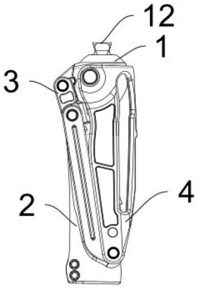
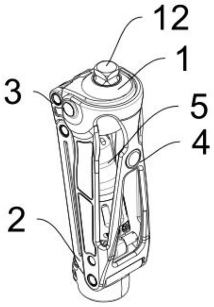
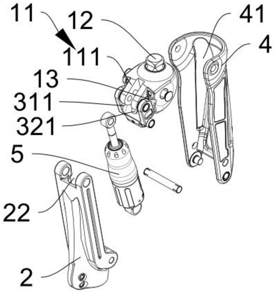
[0040] Please also refer to Figure 1 to Figure 8 , a multi-axis hydraulic knee joint provided by the present invention will now be described. The multi-axis hydraulic knee joint includes a connecting head 1, a connecting body 2, a first connecting rod 3, a second connecting rod 4, and a brake assembly 5. The connecting head 1 is provided with a protruding end 11; one end of the connecting body 2 is the connecting end, and the other end is the connecting part 21 for connecting the calf prosthesis; one end of the first connecting rod 3 is connected with the protrud...


PUM


Abstract

The invention provides a multi-shaft hydraulic knee joint, and belongs to the field of bionic devices. The multi-shaft hydraulic knee joint comprises a connector, a connecting body, a first connectingrod, a second connecting rod and a brake assembly, wherein one end of the connector is provided with a protruding end, one end of the connecting body is a connecting end, the other end of the connecting body is a connecting part for connecting a shank prosthesis, one end of the first connecting rod is connected with the protruding end by means of a rotating shaft structure, the other end of the first connecting rod is connected with the connecting end of the connecting body through a rotating shaft structure, one end of the second connecting rod is rotationally connected with the connector through a rotating shaft structure, the other end of the second connecting rod is connected with the connecting body by means of a rotating shaft structure, the brake assembly is arranged between the first connecting rod and the second connecting rod, one end of the brake assembly is rotatably connected with the protruding end through a rotating shaft structure, and the other end of the brake assembly is rotatably connected with the second connecting rod through a rotating shaft structure. The provided multi-shaft hydraulic knee joint is reasonable in structural design, small in occupied space and long in service life; and the multi-axis hydraulic knee joint also has the characteristics of high motion stability and high safety.

Description

technical field [0001] The invention belongs to the field of bionic devices, and more specifically relates to a multi-axis hydraulic knee joint. Background technique [0002] In today's society, in order to help lower limb amputee patients recover basic walking functions, prosthetic limbs are usually installed at the patient's amputation position. At the same time, in order to improve the patient's walking experience, the prosthetic limb is also equipped with a multi-axis hydraulic knee joint at the same position as the normal knee joint of the human body, so that the patient In the process of walking, the function of bending the legs can be realized. [0003] For the use of knee prostheses, it is very important to prevent the knee prosthesis from bending randomly during walking, which is the key to avoiding the user's fall; moreover, the bending frequency of the knee prosthesis has a great influence on the coordination of the user's walking during walking. Sex also plays a...

Claims


Application Information

Patent Timeline
Patent Type & Authority Applications(China)
IPC IPC(8): A61F2/64A61F2/74
CPCA61F2/64A61F2/68A61F2002/6818A61F2/74
Inventor 孙佳飞
Owner 北京市康复辅具技术中心
Why Eureka
Try Eureka