Working method for braking pedal structure capable of protecting driver and preventing leg injury

一种制动踏板、工作方法的技术,应用在制动作用启动装置、制动器、车辆部件等方向,能够解决驾驶员的脚踝或小腿受伤等问题,达到减小碰撞的效果

Inactive Publication Date: 2017-12-15
吴小再
View PDF5 Cites 2 Cited by
  • Summary
  • Abstract
  • Description
  • Claims
  • Application Information

AI Technical Summary

Problems solved by technology

The above process will greatly reduce the time for the driver to depress the brake pedal, and the impact force generated by the collision will be directly transmitted to the driver's feet through the booster device and the pedal arm, which may easily cause injuries to the driver's ankles or calves.

Method used


Image

  • Working method for braking pedal structure capable of protecting driver and preventing leg injury
  • Working method for braking pedal structure capable of protecting driver and preventing leg injury
  • Working method for braking pedal structure capable of protecting driver and preventing leg injury

Examples


Embodiment Construction

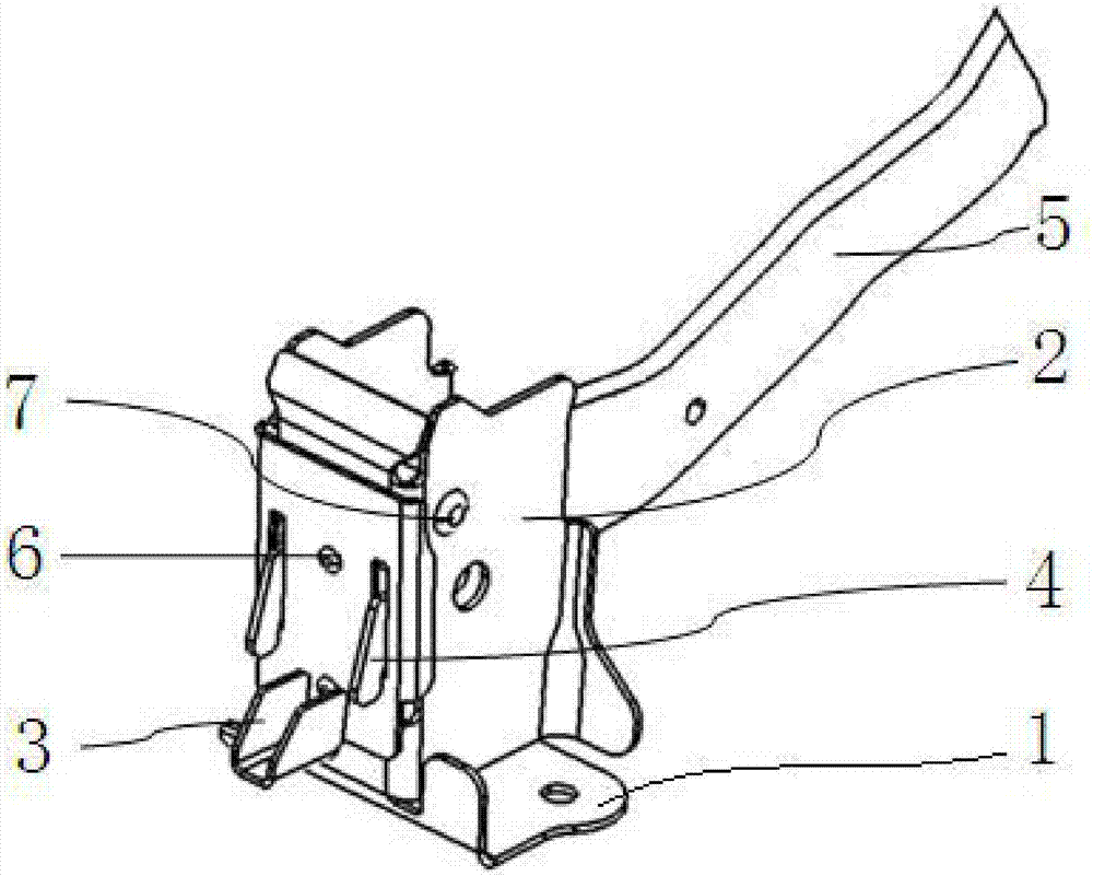
[0017] See attached picture:

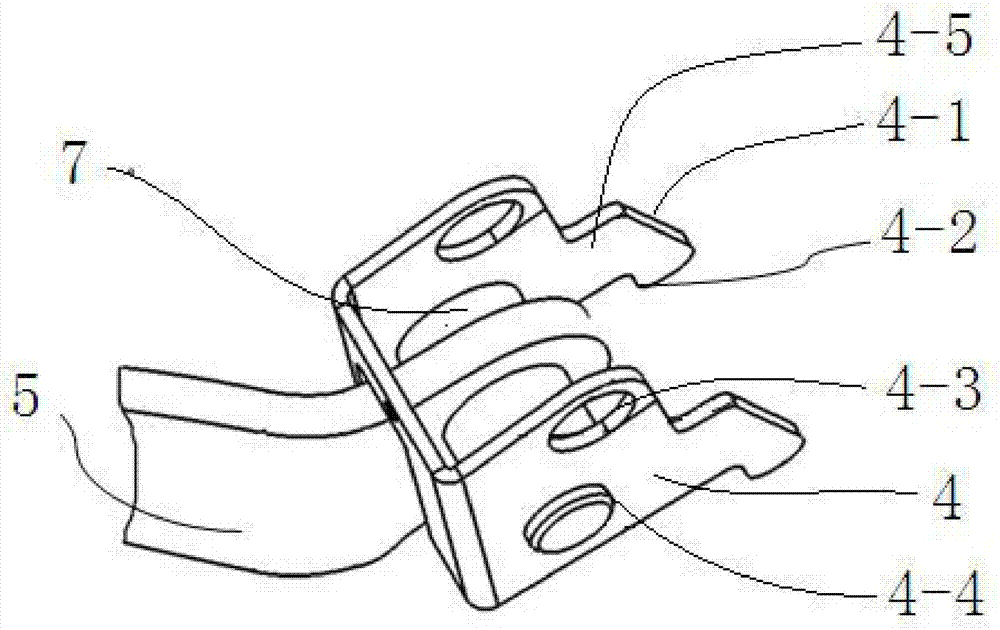
[0018] The structure of the brake pedal to prevent leg injuries includes a mounting bracket 2 installed on the upper surface of the bottom plate 1, an impact mechanism 3 is mounted on the inner wall of the mounting bracket 2, and a protection module that is rotatably installed on the front panel of the mounting bracket 2 is installed on the outside of the impact mechanism 3 4. It also includes a pedal arm 5 , which is rotatably mounted on the protection module 4 .

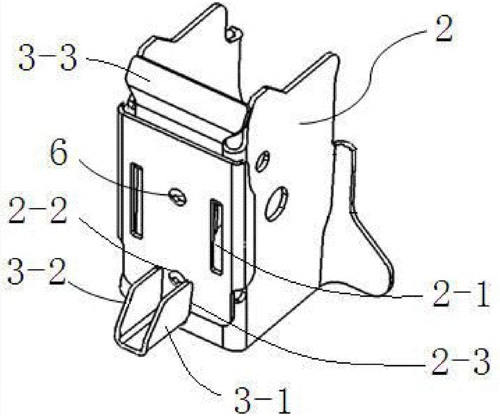
[0019] The mounting bracket 2 is a groove-shaped plate composed of a front panel and front side panels and rear side panels at both ends thereof. The front panel is provided with longitudinally spaced slots 2-1, and the slots 2-1 are longitudinally spaced. Pin holes 2-2 are distributed at intervals, wherein a mounting groove 2-3 is provided directly below the lower pin holes 2-2.

[0020] The impact mechanism 3 is a fixed plate 3-3 matched with the front panel of the mounting bracket...


PUM


Abstract

The invention discloses a working method for a braking pedal structure capable of protecting a driver and preventing leg injury. The braking pedal structure comprises a mounting bracket and a pedal arm, wherein the mounting bracket is installed on the upper end face of a bottom plate, an impacting mechanism is installed in the inner wall of the mounting bracket in an affixed mode, and a protecting module which is rotatably installed on a front panel of the mounting bracket is mounted on the outer side of the impacting mechanism; and the pedal arm is rotatably mounted on the protecting module. According to the working method for the braking pedal structure capable of protecting the driver and preventing leg injury, through reasonable structural design, great impact damage to ankle or shank of the driver due to the fact that collision occurs at the front of a vehicle and a braking pedal moves backwardly is reduced.

Description

technical field [0001] The invention relates to the field of automobile manufacturing, in particular to a brake pedal structure for preventing leg injuries. Background technique [0002] Under normal working conditions, the brake pedal arm is fixed on the pedal bracket through the rotating shaft and the pressing device. The driver depresses the pedal surface, and the pedal mechanism realizes the braking of the vehicle by means of connected structural parts such as a booster device. [0003] However, when the vehicle is running at high speed, if a frontal collision or an offset collision occurs, the front cabin will move toward the passenger compartment due to the impact, so that the brake pedal installation mechanism will also move toward the driver; in addition, in this process In the process, the driver usually also depresses the brake pedal face hard to realize the parking of the vehicle. The above-mentioned process will cause the time for the driver to depress the brake...

Claims


Application Information

Patent Timeline
Patent Type & Authority Applications(China)
IPC IPC(8): B60T7/06
CPCB60T7/065
Inventor 不公告发明人
Owner 吴小再
Why Eureka
Try Eureka