Antiseismic-collapse self-vibration-reducing structure
An anti-earthquake and self-reduction technology, applied in the direction of anti-seismic, building components, building types, etc., can solve problems such as large earthquake deformation
- Summary
- Abstract
- Description
- Claims
- Application Information
AI Technical Summary
Problems solved by technology
Method used
Image
Examples
Embodiment 1
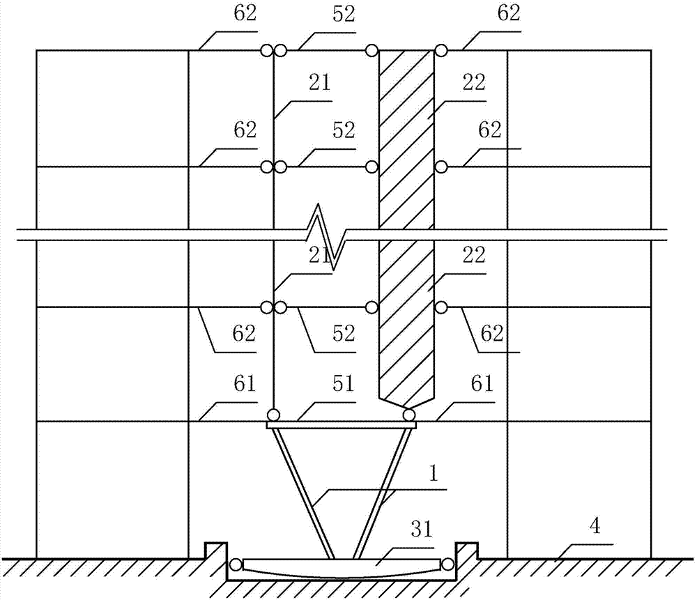
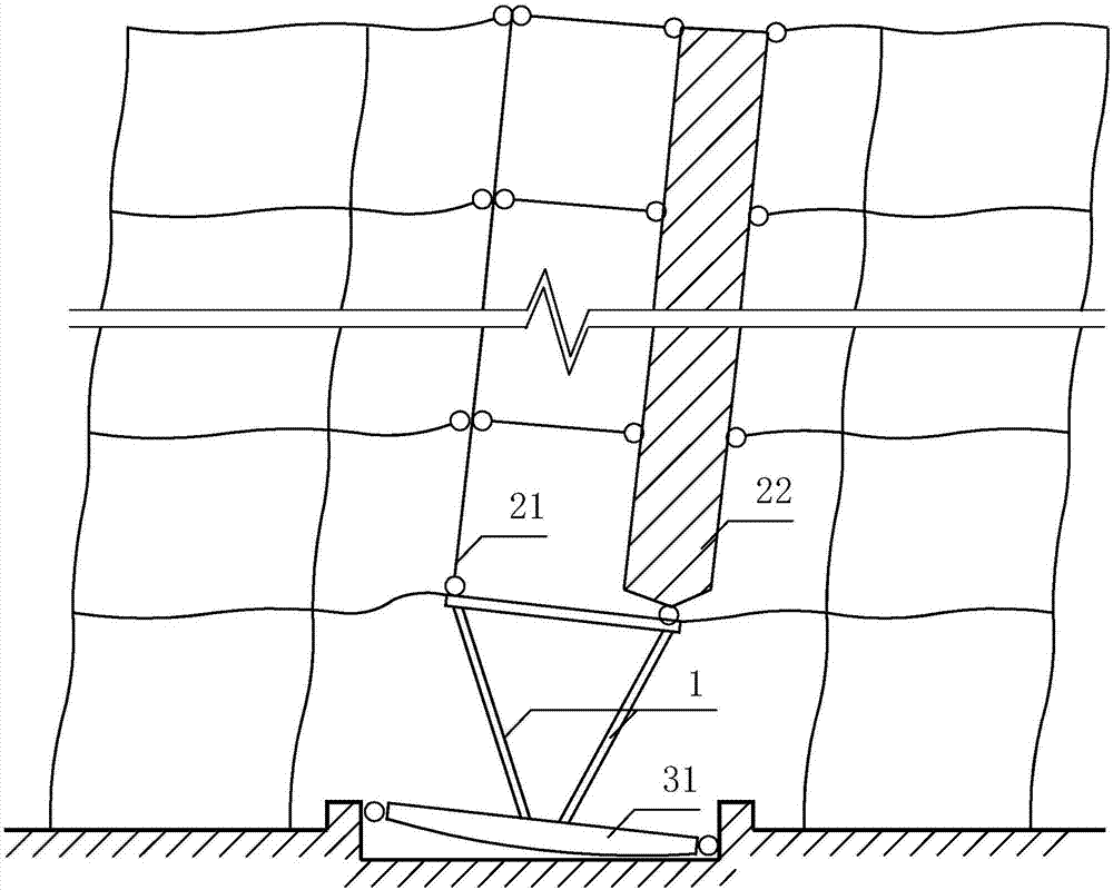
[0029] See figure 1 , figure 2 As shown, a self-damping structure for anti-seismic collapse of the present invention, the bottom layer of the structure is partially arranged with shaking members, and the left and right parts of the shaking members respectively support the upper support column 21 and the wall 22 . The components (support columns or walls) supported by the left and right parts of the shaking member are not the same member. In this embodiment, the left part of the shaking member supports the supporting column 21, and the right part of the shaking member supports the wall 22. The lower end of the shaking member is just connected with an outrigger beam 31, the axis of the outrigger beam 31 is located in the left-right direction, the outrigger beam 31 rests on the top of the foundation 4, and the outrigger beam 31 is restrained from sliding sideways relative to the foundation 4, so that the structure The stiffness of the ground floor is weakened and a structural s...
Embodiment 2
[0051] See Figure 5-Figure 6 As shown, a self-damping structure for anti-earthquake collapse of the present invention is mainly different from Embodiment 1 in that the members supported by the two upper ends of the V-shaped column 1 are all column members, that is, support columns 21, 23, The connection between the two upper ends of the V-shaped column 1 and the support columns 21, 23 is rigid connection, and the fourth beam 52 is rigidly connected between the support columns 21, 23 at the floors of each floor.
[0052] When the system encounters an earthquake, the shaking of the V-shaped column 1 will cause the support columns 21 and 23 on its two upper ends to rise, fall and move relative to each other up and down. The V-shaped column 1 and the support columns 21 and 23 on its two upper ends The corner deformation of the column section at the point, and the beam section at the connecting node between the support columns 21, 23 and the fourth beam 52 is generally much larger...
Embodiment 3
[0055] See Figure 7 As shown, a kind of anti-seismic collapse self-damping structure of the present invention is mainly different from Embodiment 1 in that: the members supported by the upper ends of the V-shaped column 1 are all column members, and the supporting columns 21, 23 are V-shaped. The mechanical model of the connection between the two upper ends of the column 1 and the support columns 21, 23 is hinged, and the support columns 21, 23 are respectively rigidly connected by fourth beams 52 at the floors of each floor.
[0056] The difference between this embodiment and Embodiment 1 is that the two upper ends of the V-shaped column 1 are connected with the surrounding ground floor, and the support columns 21, 23 are respectively connected with the surrounding floors with springs 81 and dampers 82. 81 and damper 82 are horizontally connected in parallel, and damper 82 can produce damping force in both horizontal and vertical directions.
PUM
 Abstract
Description
Claims
Application Information
 - R&D
- Intellectual Property
- Life Sciences
- Materials
- Tech Scout
- Unparalleled Data Quality
- Higher Quality Content
- 60% Fewer Hallucinations
Browse by: Latest US Patents, China's latest patents, Technical Efficacy Thesaurus, Application Domain, Technology Topic, Popular Technical Reports.
© 2025 PatSnap. All rights reserved.Legal|Privacy policy|Modern Slavery Act Transparency Statement|Sitemap|About US| Contact US: help@patsnap.com


