Shaking type self vibration reducing structure

A swaying, self-attenuating technology, which is applied to building components, protective buildings/shelters, and earthquake resistance, can solve problems such as large earthquake deformation, and achieve the effect of reducing horizontal vibration and reducing adverse effects

Pending Publication Date: 2017-11-17
HUAQIAO UNIVERSITY
View PDF7 Cites 1 Cited by
  • Summary
  • Abstract
  • Description
  • Claims
  • Application Information

AI Technical Summary

Problems solved by technology

[0004] Compared with traditional structures, rocking structures generally can greatly reduce the energy input of earthquakes to the structure, and have self-vibration damping or self-resetting capabilities, etc.; , or apply unbonded prestress, etc., requiring more careful design, construction and maintenance

Method used


Image

  • Shaking type self vibration reducing structure
  • Shaking type self vibration reducing structure
  • Shaking type self vibration reducing structure

Examples


Embodiment 1

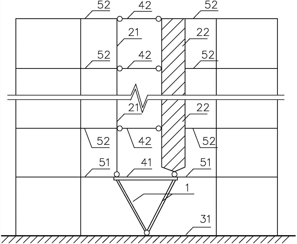
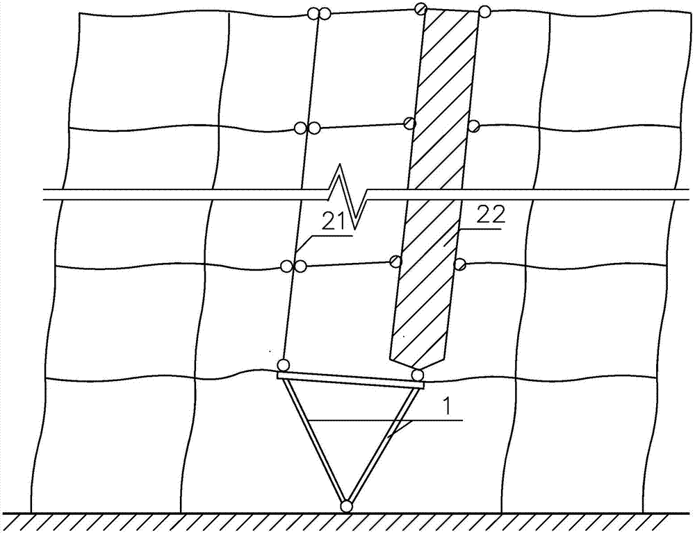
[0026] See figure 1 , figure 2 As shown, in a swaying self-damping structure of the present invention, a swaying member is partially arranged at the bottom of the structure, and the left and right parts of the swaying member respectively support the upper support column 21 and the wall 22 . The components (support columns or walls) supported by the left and right parts of the swing member are not the same component. In this embodiment, the left part of the swing component supports the support column 21, and the right part of the swing component supports the wall 22. The rocking member is supported on the top of the foundation 31, which weakens the rigidity of the floor of the structure (that is, the floor where the rocking member is located) and forms a system that can locally shake. When encountering an earthquake, the rocking member is pushed by the surrounding structures to swing back and forth, and the supporting column 21 and the wall 22 supported by the left and right ...

Embodiment 2

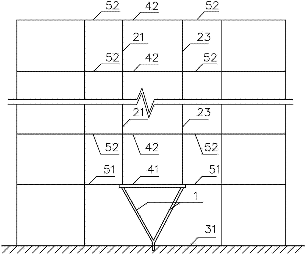
[0040] See image 3 As shown, a swaying self-damping structure of the present invention is mainly different from Embodiment 1 in that: the lower end of the V-shaped column 1 is rigidly connected to the top of the foundation 31, and the members supported by the two upper ends of the V-shaped column 1 are respectively It is the support column 21, 23, and the connection with the support column 21, 23 is a rigid connection, and the connection between the support column 21, 23 and each fourth beam 42 between them is a rigid connection.

[0041] When the system encounters an earthquake, because the V-shaped column 1 rotates around its lower end, and the supporting columns 21, 23 on its two upper ends are involved in sideways movement and relative movement up and down, the lower end of the V-shaped column, the two upper ends of the V-shaped column and the The joints of the supporting columns 21, 23, and the beam sections at the joints of the supporting columns 21, 23 and the fourth bea...

Embodiment 3

[0043] See Figure 4 As shown, a kind of swaying self-damping structure of the present invention, its main difference with embodiment two is: the lower end of V-shaped column 1 is supported on the top of beam 32 on a higher floor, and the lower end of V-shaped column 1 is connected to the floor beam The mechanical model of the connection of the 32 roof is a hinge, and the mechanical model of the connection between the upper ends of the V-shaped column 1 and the supporting columns 21, 23 is a hinge.

[0044] The left part and the right part of the rocking member refer to two parts where the rocking member is located in the lateral direction of the self-vibration-damping structure, and the two parts are separated by the position where the rocking member is supported on the floor beam 32 .


PUM


Abstract

The invention discloses a shaking type self vibration reducing structure and relates to the technical field of structural engineering earthquake resistance. The structure is provided with a swinging component in part. The left portion and the right portion of the swinging component support supporting columns or walls of the upper portion correspondingly, and / or the front portion and the rear portion of the swinging component support the supporting columns or the walls of the upper portion correspondingly. The swinging component is supported on a foundation or a floor beam to enable the structure to weaken the floor rigidity to form a partially-shaking system. The swinging component swings in a reciprocating mode when pushed by a surrounding structure, and the swinging component drives all the supporting columns or the walls which are supported by the swinging component to laterally move and move relatively vertically. Through the shaking type self vibration reducing structure, structural horizontal vibration can be effectively reduced, and the structural earthquake-resistance performance can be effectively improved.

Description

technical field [0001] The invention relates to the field of anti-seismic technology of structural engineering, in particular to a swaying self-vibration damping structure. Background technique [0002] The development of anti-seismic design technology of building structures generally goes through two approaches, that is, starting from improving the structure's own earthquake resistance, developing high-performance materials, components and structural systems, etc.; or reducing the seismic excitation response of structures through vibration control. In order to control the earthquake damage within the expected range, to achieve the level of anti-seismic fortification of the structure, so that the structure will not be damaged when it encounters an earthquake, or only damage that can be repaired quickly. There are also energy-dissipating vibration reduction or vibration isolation methods for structural seismic excitation response control, such as the installation of energy-di...

Claims


Application Information

Patent Timeline
Patent Type & Authority Applications(China)
IPC IPC(8): E04B1/98E04H9/02
CPCE04H9/02
Inventor 黄庆丰黄铮梅蔡剑华
Owner HUAQIAO UNIVERSITY
Why Eureka
Try Eureka