Air-curing frame

A technology for drying racks and limiting holes, which is applied in the field of drying racks, and can solve the problems of large occupied space, single structure of drying racks, inability to use long pole drying racks, etc., and achieve the effect of easy use and storage

Pending Publication Date: 2017-12-15
FUJIAN HAOSHIJIA BAMBOO IND CO LTD
View PDF6 Cites 1 Cited by
  • Summary
  • Abstract
  • Description
  • Claims
  • Application Information

AI Technical Summary

Problems solved by technology

[0002] The traditional drying rack is linear, the longer the length, the more objects can be hung, but the space occupied will be larger, especially when the space in the drying place is insufficient, the long pole drying rack will not be able to be used, and The existing drying racks have disadvantages such as single structure and inability to flexibly arrange according to different spaces

Method used


Image

  • Air-curing frame

Examples


Embodiment 1

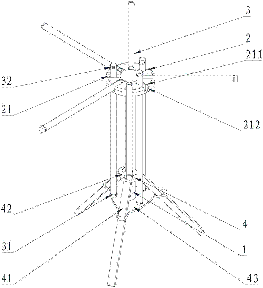
[0033] Please refer to figure 1 , Embodiment 1 of the present invention is: a drying rack, comprising a storage tray 2 with a limiting hole 21 arranged at one end of the main shaft 1 and a first limiting hole 21 passing through the limiting hole 21 and both ends are respectively sleeved. The supporting rod 3 of the position ring 31 and the second limit ring 32;

[0034] The width of the limiting hole 21 is smaller than the outer diameters of the first limiting ring 31 and the second limiting ring 32 .

Embodiment 2

[0035] Please refer to figure 1 , the second embodiment of the present invention is: a drying rack, including a storage tray 2 with a limiting hole 21 arranged at one end of the main shaft 1 and a first limiting hole 21 passing through the limiting hole 21 and two ends are respectively sleeved. The supporting rod 3 of the position ring 31 and the second limit ring 32;

[0036] The widths of the limiting holes 21 are respectively smaller than the outer diameters of the first limiting ring 31 and the second limiting ring 32 .

[0037] The middle part of the storage tray 2 is hinged to the one end of the main shaft 1 . The limiting holes 21 are arranged on the storage tray 2 in a circular array. The length of the limiting hole 21 is less than the axial distance from the first limiting ring 31 to an end of the support rod 3 close to the first limiting ring 31 . The shape of the storage tray 2 is a cylinder with a hole at the bottom, and the limit hole 21 includes a first limit ...


PUM


Abstract

The invention relates to the field of daily necessities, in particular to an air-curing frame. The air-curing frame comprises a storage disc which is arranged at one end of a main shaft and is provided with a limiting hole, and a supporting rod, wherein the two ends of the supporting rod are separately sleeved by a supporting rod of a first limiting ring and a supporting rod of a second limiting ring; and width of the limiting hole is smaller than the outer diameter of the first limiting ring and the second limiting ring. The air-curing frame provided by the invention is simple and easy to manufacture, and is convenient for air-curing use or storage.

Description

technical field [0001] The invention relates to the field of daily necessities, in particular to a drying rack. Background technique [0002] The traditional drying rack is linear, the longer the length, the more objects can be hung, but the space occupied will be larger, especially when the space in the drying place is insufficient, the long pole drying rack will not be able to be used, and The existing drying rack has the disadvantages of single structure and inability to flexibly arrange according to different spaces. Contents of the invention [0003] The technical problem to be solved by the present invention is to provide a drying rack with simple structure and convenient storage. [0004] In order to solve the above-mentioned technical problems, the technical solution adopted by the present invention is: a drying rack, comprising a storage tray with a limit hole arranged at one end of the main shaft and a first The support rod of the limit ring and the second limi...

Claims


Application Information

Patent Timeline
IPC IPC(8): F26B9/10
CPCF26B9/10
Inventor 王学琳
Owner FUJIAN HAOSHIJIA BAMBOO IND CO LTD
Why Eureka
Try Eureka