
Mobile intelligent loop closing device and application method thereof

A mobile and intelligent technology, applied in the direction of AC networks with the same frequency from different sources, can solve the problems of a large amount of money and time, long time, high investment, etc., to improve power supply reliability, simple and reasonable structure, and improve quality service horizontal effect

Active Publication Date: 2017-12-19
STATE GRID ANHUI ELECTRIC POWER CO LTD ANQING POWER SUPPLY CO +2
View PDF14 Cites 6 Cited by
  • Summary
  • Abstract
  • Description
  • Claims
  • Application Information

AI Technical Summary

Problems solved by technology

This method of operation takes a long time, is difficult and risky, and is a special operation under special circumstances.
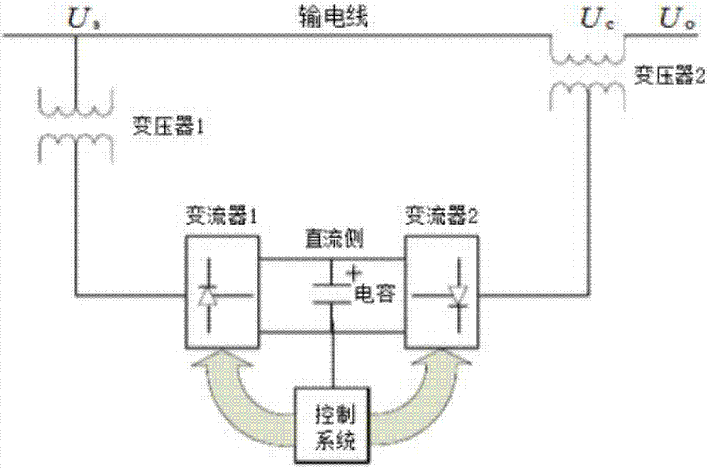
[0012] In other cases, such as the case where there is no circuit breaker, the only way to close the loop is to use a power outage, or invest a lot of money and time to transform the substation that does not meet the conditions for loop closure, which takes a long time, high investment, and economical. The benefit is low, so it is of urgent practical significance to develop a reliable mobile intelligent ring closing device to realize complete non-power-off ring closing

Method used


Image

  • Mobile intelligent loop closing device and application method thereof
  • Mobile intelligent loop closing device and application method thereof
  • Mobile intelligent loop closing device and application method thereof

Examples


Embodiment Construction

[0031] In order to make the object, technical solution and advantages of the present invention clearer, the present invention will be further described in detail below in conjunction with the accompanying drawings and embodiments. It should be understood that the specific embodiments described here are only used to explain the present invention, not to limit the present invention.

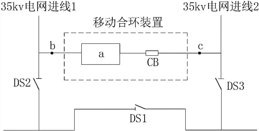
[0032] see figure 1 , figure 1 It is a structural schematic diagram of the mobile intelligent ring closing device of the present invention.

[0033] Taking the 35kv distribution network as an example, the mobile intelligent ring closing device is installed between the 35kv grid incoming line 1 and the 35kv grid incoming line 2, including phase shifting equipment a, circuit breaker CB, first spacer DS1, and second spacer DS2 and the third spacer DS3, the phase-shifting device a and the circuit breaker CB are connected in series, and are concentrated in a container or control cabinet to form an int...


PUM


Abstract

The invention relates to a mobile intelligent loop closing device. The mobile intelligent loop closing device is arranged between a power grid incoming line 1 and a power grid incoming line 2 and comprises phase shift equipment, an open-circuit switch CB, a first isolation cutter DS1, a second isolation cutter DS2 and a third isolation cutter DS3, wherein the phase shift equipment and the open-circuit switch CB are connected in series, one end of the phase shift equipment is connected with one end of the open-circuit switch CB, a first wiring terminal is led out of the other end of the phase shift equipment, a second wiring terminal is led out of the other end of the open-circuit switch CB, one end of the power grid incoming line 1 is connected with a distribution network master station, the other end of the power grid incoming line 1 is connected with the first wiring terminal and one end of the second isolation cutter DS2, the other end of the second isolation cutter DS2 is connected with a load and the first isolation cutter DS1, the power grid incoming line 2 is connected with the distribution network master station, the other end of the power grid incoming line 2 is connected with the second wiring terminal and one end of the third isolation cutter DS3, the other end of the third isolation cutter DS3 is connected with the load and the first isolation cutter DS1, and the second isolation cutter DS2 and the third isolation cutter DS3 are separately connected by the first isolation cutter DS1.

Description

technical field [0001] The invention relates to the technical field of power grid operation, in particular to a mobile intelligent loop closing device and a use method thereof. Background technique [0002] With the development of the power grid and the improvement of society's requirements for power supply reliability, the structure of the distribution network is becoming more and more complex. There are more and more cases of dual power supply or even multi-power supply power supply, and the power sensitive users are gradually increasing. Therefore, through the loop closing and unlinking operation It has become an inevitable trend to realize load switching without power failure. Its biggest advantage is that it can reduce the number of power outages for users, greatly improve the reliability of power supply, and improve the public's satisfaction with power supply. However, when the loop closing operation is performed, there will be a large impact when the loop is closed d...

Claims


Application Information

Patent Timeline
Patent Type & Authority Applications(China)
IPC IPC(8): H02J3/06
CPCH02J3/06
Inventor 桂前进江千军刘辉
Owner STATE GRID ANHUI ELECTRIC POWER CO LTD ANQING POWER SUPPLY CO
Learn More