A safe and energy-saving anti-snow device for overhead cables
An overhead cable and energy-saving technology, which is applied in the field of snow-prevention devices for safety and energy-saving overhead cables, can solve problems such as difficulty in clearing and easy accumulation of snow on overhead cables.
- Summary
- Abstract
- Description
- Claims
- Application Information
AI Technical Summary
Problems solved by technology
Method used
Image

Examples
Embodiment 1
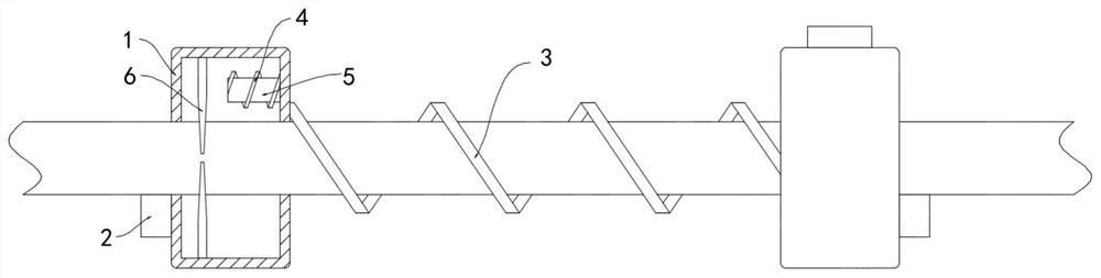
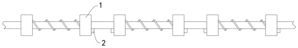
[0018] Such as Figure 1-2 As shown, a safe and energy-saving anti-snow device for overhead cables includes a plurality of snow removal parts sleeved outside the cables. The side walls of the body 1 away from each other are fixedly connected with permanent magnet blocks 2, and the multiple permanent magnet blocks 2 are all repelled by the same pole. The cable is provided with a spiral brush strip 3 formed by spirally curling long stainless steel shrapnel. The spiral brush strip 3 is attached on the surface of the cable, and the two ends of the spiral brush strip 3 are respectively fixedly connected with two annular shells 1, and the inner walls of the two annular shells 1 are fixedly connected with electromagnets 4, and the electromagnetic The iron 4 is made of silicon steel material. The two electromagnets 4 are wound with an induction coil 5. The winding directions of the two induction coils 5 are opposite. The non-contact discharge needles 6 and the two ends of the inducti...
Embodiment 2
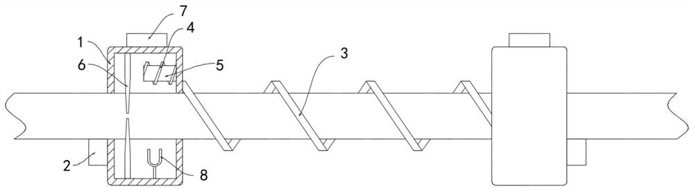
[0021] Such as image 3 As shown, the difference between this embodiment and Embodiment 1 lies in that: a whistle 7 is fixedly installed on the side wall of the annular housing 1 , and a resonant rod 8 is fixedly installed on the inner wall of the annular housing 1 .
[0022] In this embodiment, the wind in the sky blows the whistle tube 7 to make a sound, and the vibration caused drives the resonant rod 8 to vibrate. Because the inner seal of the annular shell 1 forms a resonant cavity, the vibration of the resonant rod 8 can last for a long time , Then cause the cable to vibrate, shake off the snow, and play the role of assisting snow removal.
Embodiment 3
[0024] Such as Figure 4 As shown, the difference between this embodiment and Embodiment 1 is that a horizontally arranged wing plate 9 is provided below the annular housing 1, and a horizontally arranged lifting plate 10 is slidably connected to the inner side wall of the annular housing 1. The plate 10 is fixedly connected to the wing plate 9 through the connecting rod, one of the discharge needles 6 is fixedly installed on the upper top surface of the annular housing 1, and the other discharge needle 6 is fixedly installed on the upper surface of the lifting plate 10, and the wing plate 9 is set Below the annular housing 1, the snow accumulation on the wing plate 9 can be reduced. At the same time, when the annular housing 1 moves, the wing plate 9 can be moved to shake off the snow on the wing plate 9 to ensure that the wing plate 9 can be used in snowy weather. normal work.
[0025] In this embodiment, when there is no wind and no snow, the distance between the two disch...
PUM
 Abstract
Description
Claims
Application Information
 - R&D
- Intellectual Property
- Life Sciences
- Materials
- Tech Scout
- Unparalleled Data Quality
- Higher Quality Content
- 60% Fewer Hallucinations
Browse by: Latest US Patents, China's latest patents, Technical Efficacy Thesaurus, Application Domain, Technology Topic, Popular Technical Reports.
© 2025 PatSnap. All rights reserved.Legal|Privacy policy|Modern Slavery Act Transparency Statement|Sitemap|About US| Contact US: help@patsnap.com