
Polishing machine

A technology for grinding machines and grinding discs, which is applied in the directions of grinding machine parts, grinding machines, and machine tools suitable for grinding the edges of workpieces, etc., can solve the problems of grinding machines without protective measures, reducing production efficiency, and potential safety hazards for operators, etc. Achieve the effect of avoiding waste injury incidents, speeding up production efficiency and improving safety

Inactive Publication Date: 2017-12-22
CHONGQING SANXIBAO TECH DEV
View PDF0 Cites 1 Cited by
  • Summary
  • Abstract
  • Description
  • Claims
  • Application Information

AI Technical Summary

Problems solved by technology

[0002] Burrs are usually left when parts are formed, and they need to be removed by a grinding device during finishing. Grinding machines are widely used in the foundry industry. After parts are cast and formed, they often need to use a grinding machine to grind their surfaces. In the prior art, grinding When the machine is grinding, the operator often holds it in his hand to operate, which brings great danger to the operator's production. In the prior art, the grinding disc of the general grinding machine is fixed at a fixed point. Due to the difference in shape and size of the accessories, the In the process of grinding different accessories, it is often necessary to adjust the position of the grinding disc, which is extremely inconvenient to use. This not only consumes labor and time, but also greatly reduces production efficiency. The existing grinding machine does not have any protective measures. Waste is easy to hurt people and brings certain hidden dangers to the safety of operators

Method used


Image

  • Polishing machine
  • Polishing machine
  • Polishing machine

Examples


Embodiment Construction

[0016] The following will clearly and completely describe the technical solutions in the embodiments of the present invention with reference to the accompanying drawings in the embodiments of the present invention. Obviously, the described embodiments are only some, not all, embodiments of the present invention. Based on the embodiments of the present invention, all other embodiments obtained by persons of ordinary skill in the art without making creative efforts belong to the protection scope of the present invention.

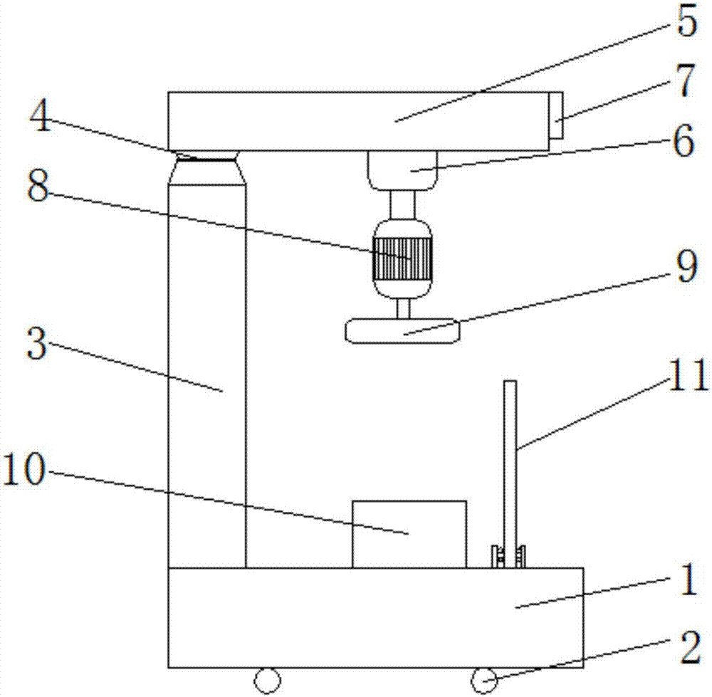
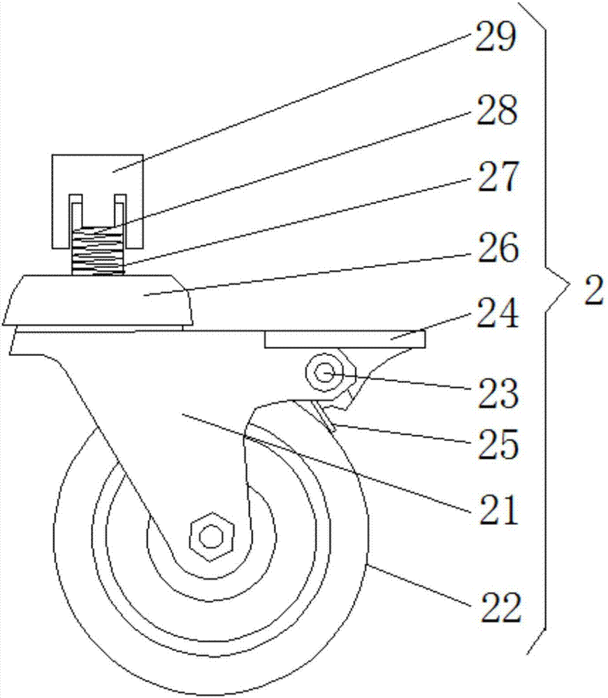
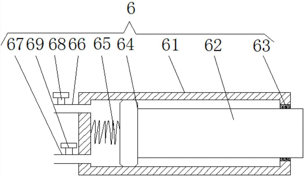
[0017] see Figure 1-5 , the present invention provides a technical solution: this kind of mechanical and electrical accessories grinding machine includes a base 1, the bottom of the base 1 is fixed with a locking universal wheel 2, the locking universal wheel 2 includes a bracket 21, and the bottom of the bracket 21 is rotatably connected There is a runner 22, the top side of the support 21 is interspersed with a rotating rod 23, the rotating rod 23 is fixedl...


PUM


Abstract

The invention discloses a grinding machine, comprising a base, the bottom of the base is fixedly provided with a locking universal wheel, the locking universal wheel comprises a bracket, the bottom of the bracket is rotatably connected with a runner, and the bracket The top side of the bracket is interspersed with a rotating rod, the rotating rod is fixedly connected with a locking plate, and the bottom of the locking plate is provided with a locking piece, the top of the bracket is provided with a rotating block, and the top of the rotating block is provided with a rotating block. A support rod is fixedly connected. The electromechanical accessories grinding machine is widely used in the foundry industry. By improving the grinding machine with clamping device, the danger caused by the operator's hand-holding is avoided. By adding a rotating device to the grinding machine, the angle of the grinding disc can be adjusted. , which is very convenient for the operator to use. By installing a protective plate on the grinding machine, the waste is placed in the protective plate during grinding, which avoids the occurrence of the accident of the waste injuring people, and improves the safety of the operator's production.

Description

technical field [0001] The invention relates to the technical field of grinding machines, in particular to a grinding machine. Background technique [0002] Burrs are usually left when parts are formed, and they need to be removed by a grinding device during finishing. Grinding machines are widely used in the foundry industry. After parts are cast and formed, they often need to use a grinding machine to grind their surfaces. In the prior art, grinding When the machine is grinding, the operator often holds it in his hand to operate, which brings great danger to the operator's production. In the prior art, the grinding disc of the general grinding machine is fixed at a fixed point. Due to the difference in shape and size of the accessories, the In the process of grinding different accessories, it is often necessary to adjust the position of the grinding disc, which is extremely inconvenient to use. This not only consumes labor and time, but also greatly reduces production effi...

Claims


Application Information

Patent Timeline
IPC IPC(8): B24B9/04B24B41/06B24B41/00B24B55/00B24B47/10
CPCB24B9/04B24B41/00B24B41/06B24B47/10B24B55/00
Inventor 谢小波
Owner CHONGQING SANXIBAO TECH DEV
Learn More