Structure of connecting shear walls and coupling beam by U-shaped steel bars and connecting pieces, and assembling method

A technology of connectors and shear walls, applied in the direction of walls, building components, building structures, etc., can solve the problems of inapplicability and high technical requirements for grouting, and achieve the effects of high assembly rate, shortened construction period, and improved assembly degree.

Pending Publication Date: 2017-12-22
SHENYANG JIANZHU UNIVERSITY
View PDF5 Cites 1 Cited by
  • Summary
  • Abstract
  • Description
  • Claims
  • Application Information

AI Technical Summary

Problems solved by technology

[0004] In order to solve the above problems, in previous inventions, "Assembly connection structure of shear wall coupling beam of prefabricated concrete frame shear structure (CN201420657677.8), assembly connection structure and method of prefabricated concrete frame shear structure shear wall coupling beam (CN201410616527.7)", mainly using the idea of ​​equivalent replacement of steel bars, that is, using a single single-row steel bar to be equivalent to multiple multi-row steel bars, which requires high grouting technology during construction, and when the coupling beam section or reinforcement is large This method is not applicable when

Method used


Image

  • Structure of connecting shear walls and coupling beam by U-shaped steel bars and connecting pieces, and assembling method
  • Structure of connecting shear walls and coupling beam by U-shaped steel bars and connecting pieces, and assembling method
  • Structure of connecting shear walls and coupling beam by U-shaped steel bars and connecting pieces, and assembling method

Examples


specific Embodiment approach

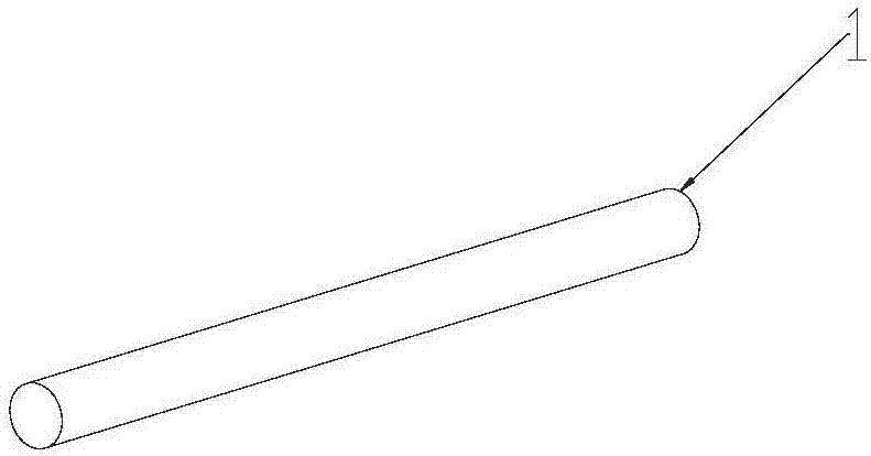
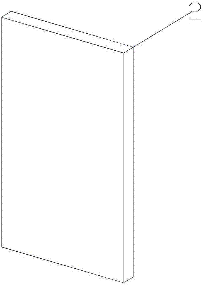
[0050] like Figure 1 to Figure 19 As shown, the prefabricated concrete U-shaped steel bar-connector of the present invention connects the shear wall coupling beam structure and assembly method, including two specific implementation modes, specifically as follows:

[0051] (one) Figure 1-Figure 16 As shown, when the length of the connecting beam of the shear wall in the prefabricated concrete frame-shear structure is greater than 3m or the project has clear requirements, the two ends of the connecting beam and the connection position of the shear wall are split to form two prefabricated walls 11 and A prefabricated coupling beam 15 constitutes a structural disassembly and assembly system.

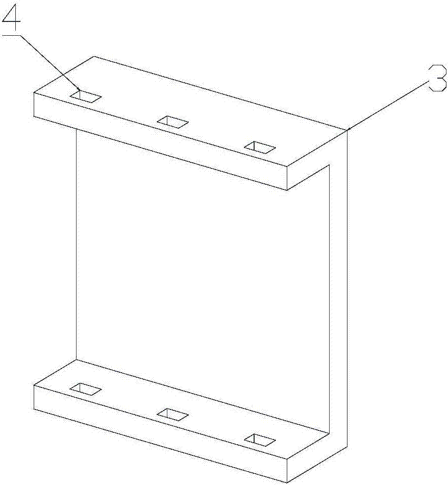
[0052] (1) In order to realize the connection between the prefabricated wall 11 and the prefabricated connecting beam 15 , the embedded connecting piece 5 is arranged in the prefabricated wall 11 and the prefabricated connecting beam 15 .

[0053] like Figure 1-Figure 4 As shown, the e...


PUM


Abstract

The invention relates to the field of assembly type concrete structures, and specifically relates to a structure of connecting shear walls and a coupling beam by U-shaped steel bars and connecting pieces, and an assembling method. A structure splitting and assembling system is formed by a coupling beam in prefabricated shear walls, and prefabricated shear walls, or a coupling beam of a shear wall with a half-span coupling beam, and U-shaped connecting steel bars, and the connecting pieces are pre-embedded in the prefabricated coupling beam, the prefabricated wall or the prefabricated wall with a beam. When the coupling beam of the shear walls in the assembly type concrete frame-shear wall structure is long, splitting is carried out at positions where two ends of the coupling beam are connected with the shear walls, and the prefabricated coupling beam and the two prefabricated walls connected with beam ends of the prefabricated coupling beam are respectively manufactured; and when the coupling beam of the shear walls in the assembly type concrete frame-shear wall structure is short, splitting is carried out at the midspan position of the coupling beam, and two prefabricated walls with a beam are formed after splitting is carried out, and the connection method is mentioned above. Connection of the shear walls and the coupling beam is achieved by the U-shaped steel bars and the connecting pieces, components are simple and workable, the assembling process is simple, time is saved and efficiency is high, and applicability is wide.

Description

technical field [0001] The invention relates to the field of prefabricated concrete structures, in particular to a U-shaped steel bar-connector connection shear wall coupling beam structure and an assembly method, especially a prefabricated concrete frame composed of prefabricated coupling beams, prefabricated walls or prefabricated beam walls The disassembly and assembly system of the shear wall with coupling beams in the shear structure, the connection structure of the components, the structures built by this assembly system and the connection structure, and the assembly connection method. Background technique [0002] Frame-shear wall structure, referred to as frame-shear structure, the main structure is frame and shear wall, in which the frame is composed of beams and columns, and the shear wall is arranged in part of the frame, and the shear wall is used to increase the horizontal load resistance of the overall structure ability. The frame-shear structure is suitable f...

Claims


Application Information

Patent Timeline
Patent Type & Authority Applications(China)
IPC IPC(8): E04B2/56E04B1/38E04G21/14
CPCE04B1/38E04B2/56E04G21/14
Inventor 李明郭伟强李爽杨永强
Owner SHENYANG JIANZHU UNIVERSITY
Why Eureka
Try Eureka