Touch display panel, driving method and production method thereof and touch display device

A technology of a touch display panel and a touch signal line, applied in the fields of a touch display device, a touch display panel and its driving method, and a manufacturing method, capable of solving problems such as unfavorable touch display panel narrow frame design and complicated process

Active Publication Date: 2017-12-26
BOE TECH GRP CO LTD +1
View PDF5 Cites 14 Cited by
  • Summary
  • Abstract
  • Description
  • Claims
  • Application Information

AI Technical Summary

Problems solved by technology

A capacitive touch sensing unit usually includes an emitter electrode and a sensing electrode. When manufacturing a touch display panel, it is usually necessary to use a patterning process to form the emitter electrode and sensing electrode of the touch sensing unit, resulting in The process is complex; at the same time, in the existing touch display panel, the emitter electrodes are usually arranged along the direction parallel to the gate lines, the sensing electrodes are usually arranged along the direction parallel to the data lines, and the emitter electrodes located in the same row are Lines parallel to the emitter electrode line connection, the emitter electrode line needs to pass through the borders on both sides of the touch display panel to connect with the touch driver chip, so it is necessary to reserve a space for the arrangement of the emitter electrode line on the borders on both sides of the touch display panel The space is not conducive to the narrow frame design of the touch display panel

Method used


Image

  • Touch display panel, driving method and production method thereof and touch display device
  • Touch display panel, driving method and production method thereof and touch display device
  • Touch display panel, driving method and production method thereof and touch display device

Examples


Embodiment Construction

[0070] In order to further illustrate the touch display panel provided by the embodiments of the present invention, its driving method, manufacturing method, and touch display device, a detailed description will be given below in conjunction with the accompanying drawings.

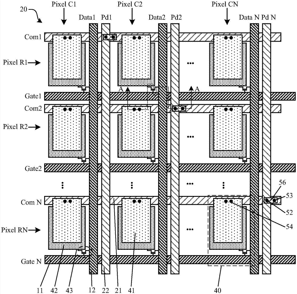
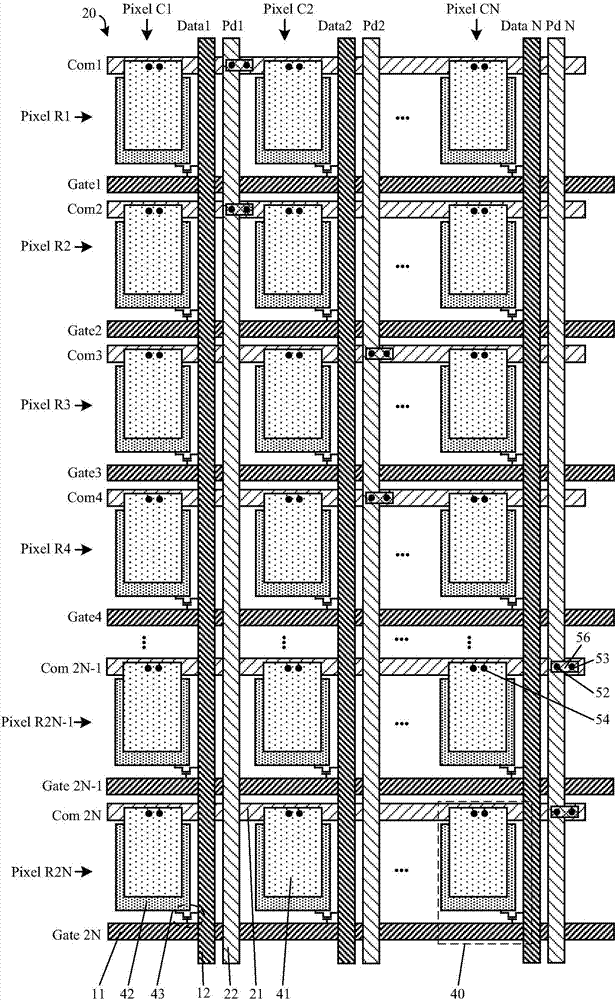
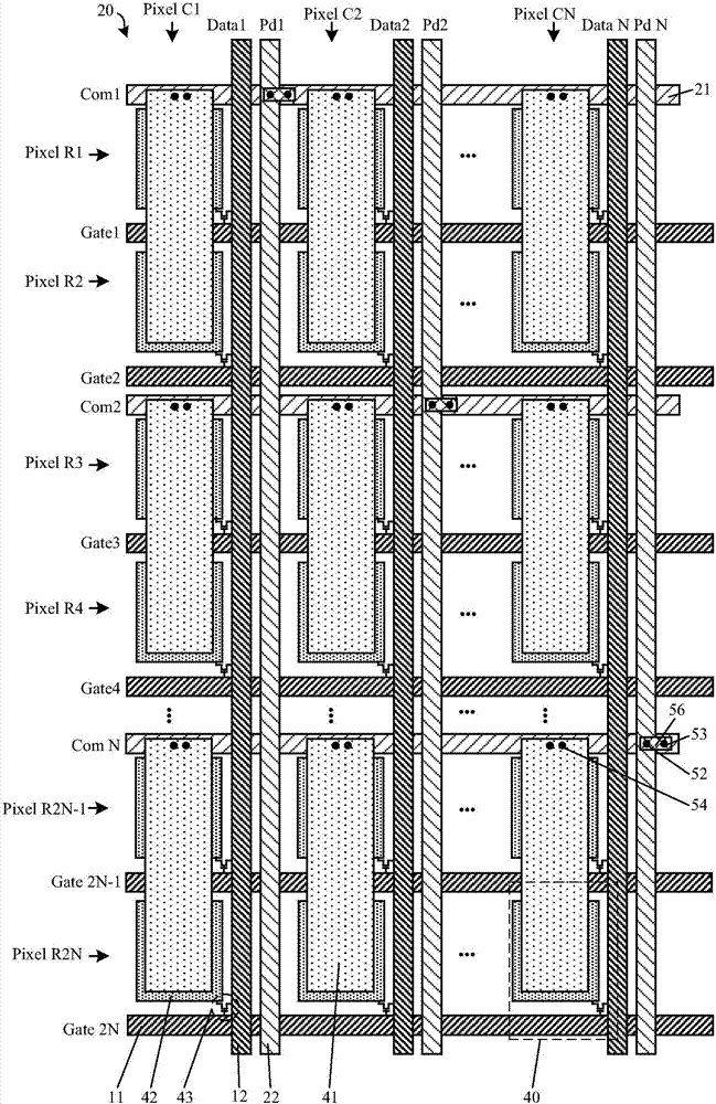
[0071] see figure 1 , figure 2 or image 3 , the touch display panel provided by the embodiment of the present invention includes a plurality of gate lines 11, a plurality of data lines 12 and a plurality of common electrodes 41; along a direction parallel to the gate lines 11, the touch display panel includes one or more The touch area 20, the touch area 20 includes a plurality of common electrode lines 21 and a plurality of touch signal lines 22, the number of the common electrode lines 21 is greater than or equal to the number of the touch signal lines 22; wherein, the common electrode lines 21 and the grid The lines 11 are parallel, each common electrode line 21 is connected to the common electrode ...


PUM


Abstract

The invention discloses a touch display panel, a driving method and a production method thereof and a touch display device, and relates to the technical field of touch display. The touch display panel comprises grid lines, data lines and common electrodes; in the direction parallel to the grid lines, the touch display panel comprises one or more touch subareas, each touch subarea comprises common electrode lines and touch signal lines, and the common electrode lines are parallel to the grid lines and connected with the corresponding common electrodes; the touch signal lines are parallel to the data lines, and each touch signal line is connected with at least one common electrode line; the touch signal lines and the common electrode lines are used for transmitting display potential signals to the corresponding common electrodes in a display time interval of each frame, transmitting touch driving signals to the common electrodes in a touch time interval of each frame line by line and transmitting touch sensing signals.

Description

technical field [0001] The present invention relates to the technical field of touch display, in particular to a touch display panel, a driving method thereof, a manufacturing method, and a touch display device. Background technique [0002] A touch display device is a device that can realize both display and touch control. At present, a touch display device usually includes a touch display panel, and a touch display panel usually includes a display panel and a touch panel. According to the touch panel and The relative positional relationship of the display panel can be divided into a built-in touch display panel and an out-cell touch display panel (Out-cell). Touch display panel (In-cell) and built-in surface touch display panel (On-cell), because the built-in in-plane touch display panel (In-cell) is easy to manufacture thinner and lighter products, it has been extensively researched and application. [0003] In the existing built-in in-plane touch display panel (In-cell...

Claims


Application Information

Patent Timeline
IPC IPC(8): G06F3/044G06F3/041
CPCG06F3/0412G06F3/0416G06F3/044G06F2203/04103G06F3/04164G06F3/04166G06F3/04184G06F3/0443G06F3/0446H01L29/42384
Inventor 胡祖权马小叶马睿
Owner BOE TECH GRP CO LTD
Why Eureka
Try Eureka