Rubber V-belt round mould vulcanizing device

A round mold and rubber technology, applied in belts, other household appliances, household appliances, etc., can solve problems such as energy waste, save steam, ensure the quality of vulcanization molding, and reduce energy waste.

Active Publication Date: 2017-12-29
ZHEJIANG SANWEI RUBBER ITEM CO LTD
View PDF6 Cites 2 Cited by
  • Summary
  • Abstract
  • Description
  • Claims
  • Application Information

AI Technical Summary

Problems solved by technology

The current rubber V-belt vulcanization tank needs to be fed with a large amount of saturated steam during vulcanization, and the steam in the vulcanization tank needs to be discharged after the rubber V-belt vulcanization is completed, which causes a lot of energy waste

Method used


Image

  • Rubber V-belt round mould vulcanizing device
  • Rubber V-belt round mould vulcanizing device
  • Rubber V-belt round mould vulcanizing device

Examples


Embodiment 1

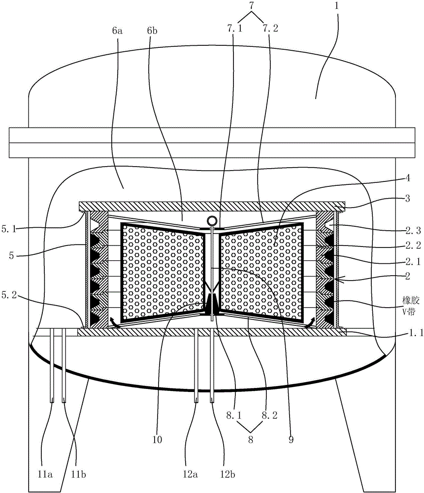
[0045] Embodiment 1: as figure 1 As shown, a rubber V-belt round mold vulcanization device includes: a vulcanization tank 1, a V-belt vulcanization mold sleeve 2, a vulcanization sealing rubber sleeve 5 set outside the V-belt vulcanization mold sleeve, a mold sealing cover plate 3 and a steam-saving Energy saving parts4. The bottom of the cavity of the vulcanization tank is provided with a support plate 1.1.

[0046] The lower end surface of the V-belt vulcanization die sleeve is supported on the upper surface of the supporting plate. The axis of the V-belt vulcanization mold sleeve is set vertically. The outer surface of the V-belt vulcanization die sleeve is provided with a number of annular V-belt forming grooves 2.3 distributed sequentially from bottom to top. The V-belt vulcanization die sets include sequentially distributing individual die sets 2.1 from bottom to top and a die set connection structure connecting the individual die sets. The annular V-belt forming gro...

Embodiment 2

[0064] Embodiment 2: the remaining structure of this embodiment is with reference to embodiment 1, and its difference is:

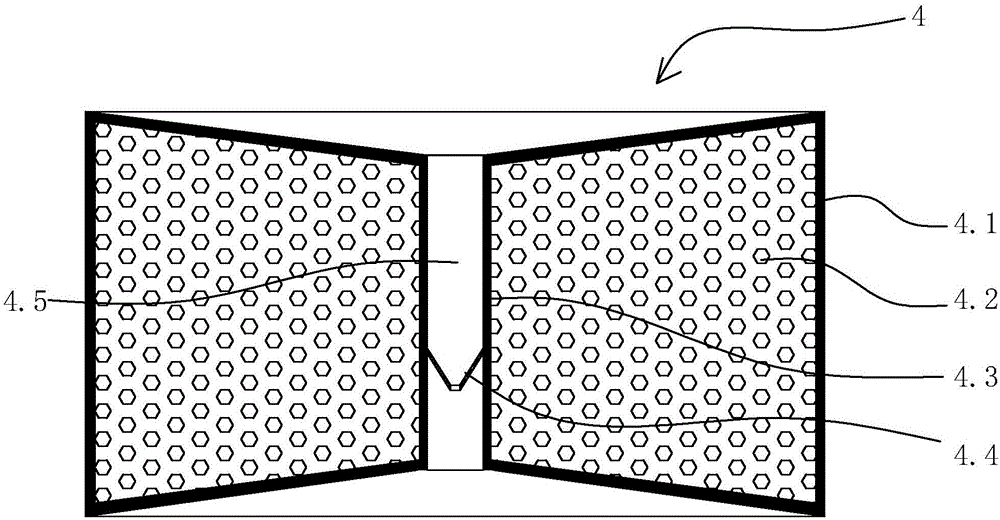
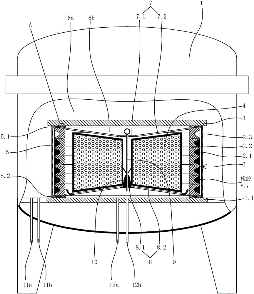
[0065] Such as image 3 , Figure 4 As shown, the upper end of the vulcanized sealing rubber sleeve 5 is provided with an annular upper sealing sheet 5.1 extending inward, that is, the upper end of the vulcanized sealing rubber sleeve is provided with an annular upper sealing sheet extending into the vulcanized sealing rubber sleeve. The annular upper sealing piece is located between the upper end surface of the V-belt vulcanization mold sleeve and the mold sealing cover plate, and the annular upper sealing piece forms a sealing structure between the upper end surface of the V-belt vulcanization mold sleeve and the mold sealing cover plate.

[0066] The lower end of the vulcanized sealing rubber sleeve is provided with an annular lower sealing sheet 5.2 extending inward, that is, the lower end of the vulcanized sealing rubber sleeve is provided with an a...


PUM


Abstract

The invention discloses a rubber V-belt round mould vulcanizing device. According to the rubber V-belt round mould vulcanizing device, under the premise that the vulcanizing effect of a rubber V belt is not influenced, steam led into a vulcanizing tank can be effectively reduced, and the steam exhausting amount is reduced after the rubber V belt is vulcanized, so that the steam is saved, and energy waste is reduced. The rubber V-belt round mould vulcanizing device comprises the vulcanizing tank, a V-belt vulcanizing mould sleeve, a mould sealing cover plate and a steam-saving energy-saving part, wherein the bottom of a cavity of the vulcanizing tank is provided with a supporting flat plate; the lower end surface of the V-belt vulcanizing mould sleeve is supported by the upper surface of the supporting flat plate, and a plurality of annular V-belt molding grooves are formed in the outer side surface of the V-belt vulcanizing mould sleeve from bottom to top in sequence; the mould sealing cover plate is supported by the upper end surface of the V-belt vulcanizing mould sleeve; and the steam-saving energy-saving part is arranged in the V-belt vulcanizing mould sleeve, and an annular circulating cavity used for allowing the steam to be circulated is arranged between the outer side surface of the steam-saving energy-saving part and the inner side surface of the V-belt vulcanizing mould sleeve.

Description

technical field [0001] The invention relates to a curing device, in particular to a rubber V-belt circular die curing device. Background technique [0002] When the current rubber V-belt enters the vulcanization tank for vulcanization, a certain pressure of saturated steam is passed inside and outside the V-belt round mold. After a certain period of vulcanization, after the vulcanization of the rubber V-belt is completed, the steam in the vulcanization tank needs to be discharged, and then taken out. Vulcanized rubber V-belt. The current rubber V-belt vulcanization tank needs to feed a large amount of saturated steam during vulcanization, and the steam in the vulcanization tank needs to be discharged after the rubber V-belt vulcanization is completed, which causes a lot of energy waste. Contents of the invention [0003] The object of the present invention is to provide a rubber V-belt circular mold vulcanization device, which can effectively reduce the steam passing into...

Claims


Application Information

Patent Timeline
Patent Type & Authority Applications(China)
IPC IPC(8): B29C35/06B29L29/00
CPCB29C35/049B29C35/06B29L2029/00
Inventor 何良叶军李晓林
Owner ZHEJIANG SANWEI RUBBER ITEM CO LTD
Why Eureka
Try Eureka