Interpositional ophthalmological implant

An implant and ophthalmic technology, applied in ophthalmic surgery, ophthalmic treatment, medical science, etc., can solve the problem of insufficient IOP and achieve the effect of easy installation and removal

Active Publication Date: 2018-01-02
希里亚泰克公司
View PDF9 Cites 0 Cited by
  • Summary
  • Abstract
  • Description
  • Claims
  • Application Information

AI Technical Summary

Problems solved by technology

[0009] IOP reduction obtained by these techniques is usually insufficient and temporary

Method used


Image

  • Interpositional ophthalmological implant
  • Interpositional ophthalmological implant
  • Interpositional ophthalmological implant

Examples


Embodiment Construction

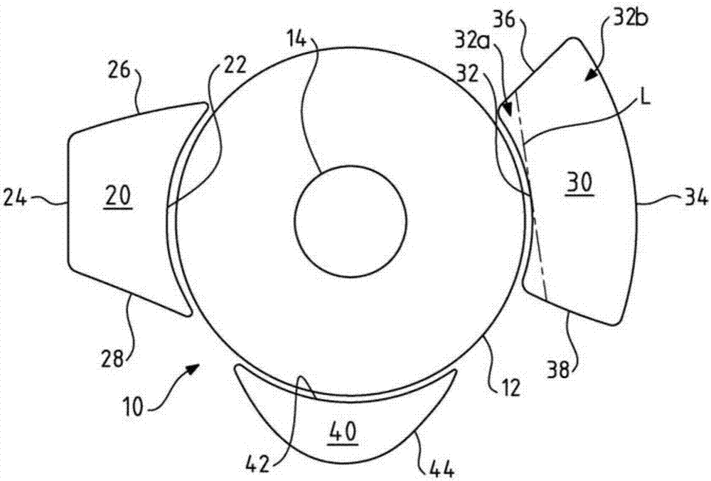
[0056] The present invention relates to an ophthalmic implant intended to be permanently implanted between the tissues of the sclera and the uvea, and thus permanently positioned between these tissues.

[0057] The implant according to the present invention comprises a thin-walled body so that once inserted between the sclera and uveal tissue, it does not deform the overlying and underlying tissue to an unacceptable degree. Acceptable deformation of tissues is one that does not impair the function of either or both of these tissues.

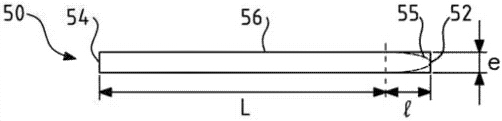
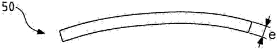
[0058] The body of the implant has three dimensions in space: a thickness, a length perpendicular to the thickness and a width (or two equal dimensions if the length and width are equal). A "thin-walled body" is to be understood as a body whose thickness is at least 10 times less than the shortest of the other two dimensions of the body (ie the width, or either if the two other dimensions are equal). In an exemplary embodiment, the thickness is ...


PUM


Abstract

The invention relates to a permanent interpositional ophthalmological implant between the sclera and the uveal tissue. The implant comprises a thin uvea-compatible body (50) having a thickness (e) which is at least less than 10 times the smallest of the two other dimensions of the body, the body of the implant comprising two opposing edges separated from one another along one of the two dimensionsperpendicular to the thickness, and one of the edges, known as the front edge (52), being curved in a concave manner away from body in a plane perpendicular to the thickness.

Description

technical field [0001] The present invention relates to interpositional ophthalmological implants for keeping the sclera and ciliary body permanently separated from each other in order to lower intraocular pressure (IOP). Background technique [0002] Intraocular pressure is the result of a balance between secretions produced by the ciliary body and the flow of these secretions through Schlemm's canal through the corneoscleral trabecular meshwork and out into the aqueous humor veins and the general circulation. 10% to 15% of this stream flows directly through the ciliary trabeculae between the sclera and the ciliary body, which is known as the uveal-scleral flow. The longitudinal fibers of the ciliary muscle, especially during adaptation, act to tighten the trabecular meshwork to facilitate uveo-scleral flow of aqueous humor. [0003] In glaucoma, the flow of aqueous humor in the trabeculae is reduced, which in most cases leads to an increase in intraocular pressure (IOP). ...

Claims


Application Information

Patent Timeline
Patent Type & Authority Applications(China)
IPC IPC(8): A61F9/007
CPCA61F9/00781A61F2250/0009A61F9/0017
Inventor 菲利普·苏尔迪耶
Owner 希里亚泰克公司
Why Eureka
Try Eureka