
Electrical connectors and electrical connector assemblies

A technology for electrical connectors and contacts, applied in vehicle connectors, parts of connecting devices, connections, etc.

Inactive Publication Date: 2019-07-09
TYCO ELECTRONICS JAPAN GK +1
View PDF6 Cites 0 Cited by
  • Summary
  • Abstract
  • Description
  • Claims
  • Application Information

AI Technical Summary

Problems solved by technology

[0003] For example, Patent Document 1 points out that water diffuses along the tiny gap between the male housing and the female housing due to capillary action, and may reach the terminal insertion hole located on the deep side in the mating direction.

Method used


Image

  • Electrical connectors and electrical connector assemblies
  • Electrical connectors and electrical connector assemblies
  • Electrical connectors and electrical connector assemblies

Examples


no. 1 approach

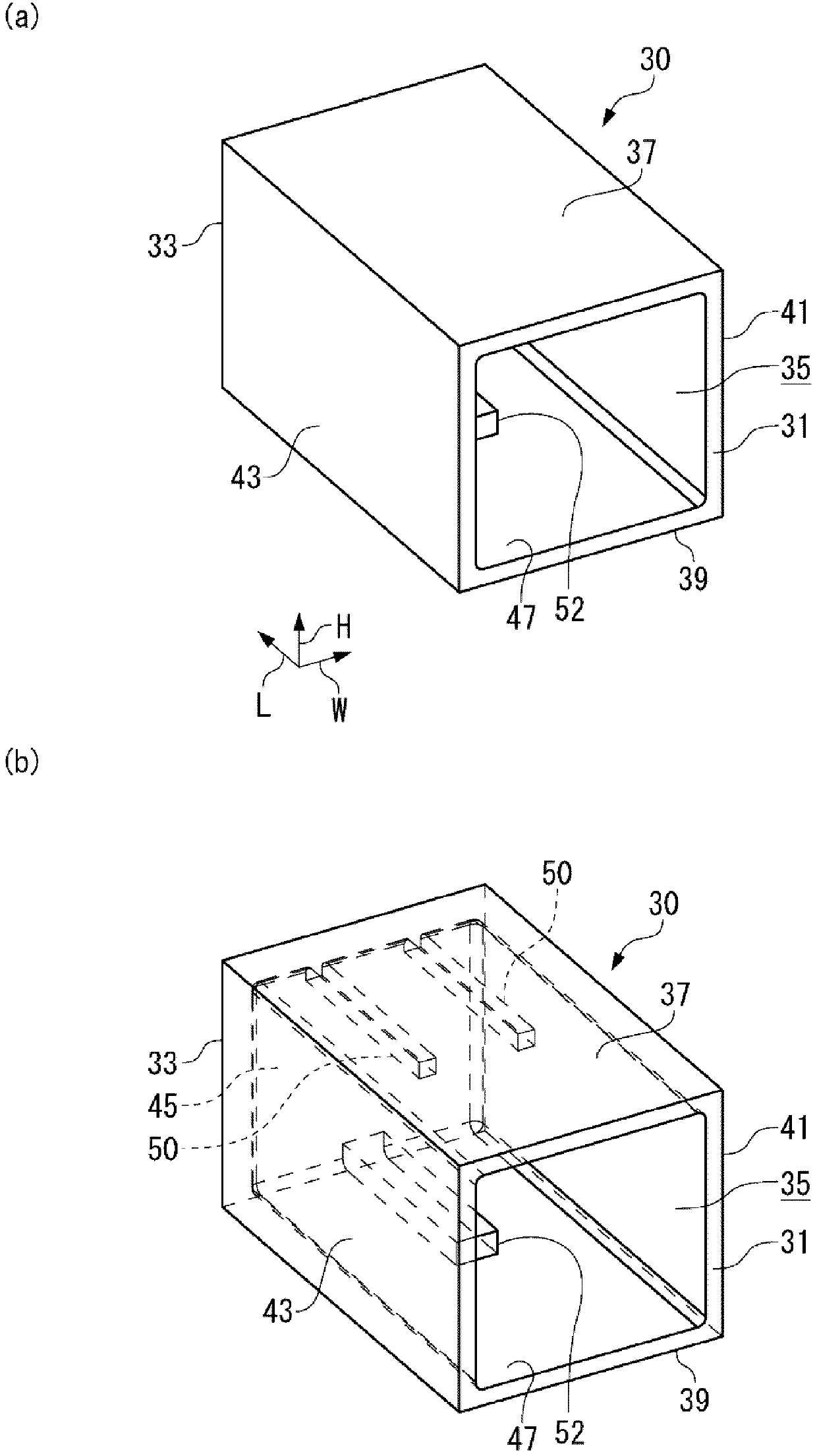
[0033] The electrical connector assembly 1 related to the first embodiment is as Figure 1 ~ Figure 3 As shown, a male housing 10 and a female housing 30 are provided. The male housing 10 constitutes the electrical connector (first electrical connector) of the present invention by holding a female contact (not shown), and the female housing 30 holds a male contact (not shown). The components are held to constitute the mating-side electrical connector (second electrical connector) of the present invention. When the male housing 10 and the female housing 30 are fitted together, the female contact and the male contact are electrically connected. Hereinafter, after describing the structure of the male housing 10 and the female housing 30 in order, the functions and effects of the electrical connector assembly 1 will be described.

[0034] [male housing 10]

[0035] The male housing 10 is a member obtained by injection molding a resin having electrical insulation properties, suc...

no. 2 approach

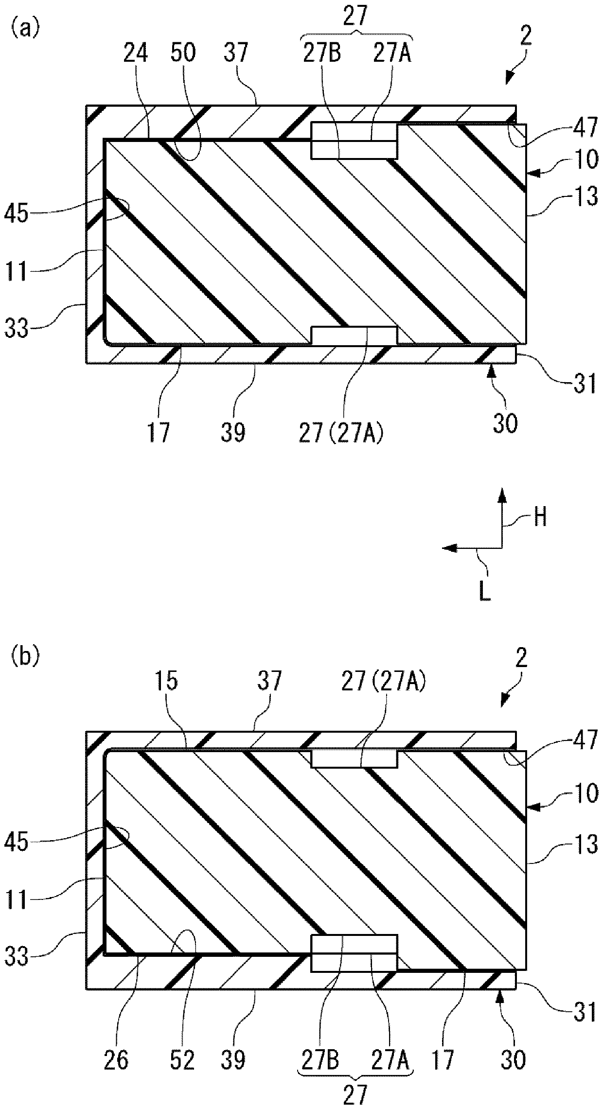
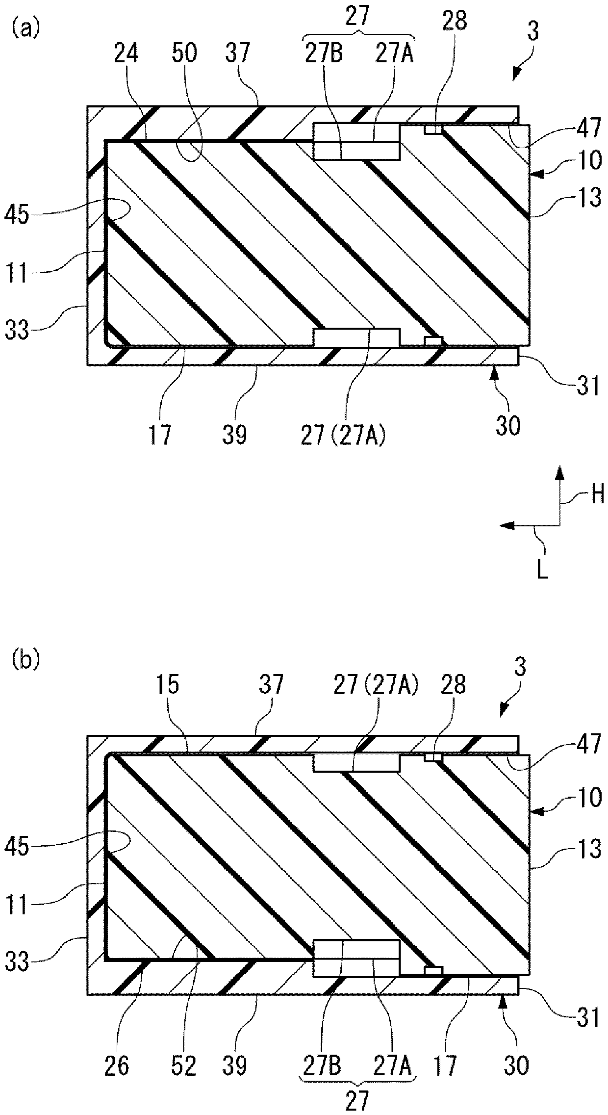
[0062] Next, refer to Figure 4 ~ Figure 6 The electrical connector unit 2 according to the second embodiment of the present invention will be described.

[0063] The electrical connector assembly 2 is consistent with the electrical connector assembly 1 in that a certain waterproof performance is ensured by setting the water stop groove 27 . However, in the electrical connector assembly 2 , the upper guide groove 24 , the lower guide groove 26 , the upper guide bar 50 , and the lower guide bar 52 are limited to the deeper side than the water stop groove 27 in order to improve the waterproof performance. In addition, in the electrical connector assembly 2, for the same elements as the electrical connector assembly 1, for Figure 4 ~ Figure 6 attached with Figure 1 ~ Figure 3 same symbols, and their descriptions are omitted.

[0064] Electrical connector assembly 2 such as Figure 6 (a), (b), in the male housing 10, a pair of upper guide grooves 24, 24 and lower guide groov...


PUM


Abstract

An object of the present invention is to provide an electrical connector capable of ensuring waterproof performance even when exposed to an increased amount of water. The present invention comprises a male housing (10), and a water stop groove (27) extending along the circumferential direction of the male housing (10), which is perpendicular to the mating direction (L) with the female housing (30). ). Water (WD) flows toward the front end (11) of the male housing (10) due to capillary action. However, when the front edge (29) of the water stop groove (27) is reached, the upper wall (37) disappears, so that the water (WD) is exposed to a large space from the previous narrow space. Thus, on the front side of the male housing (10) compared to the leading edge (29), the capillary phenomenon is eliminated, and on the contrary, since the surface tension (ST) is generated in the water (WD), the water (WD) tends to interact with the The leading edge (29) stays behind in comparison.

Description

technical field [0001] The invention relates to an electrical connector, in particular to an electrical connector with mild waterproof performance. Background technique [0002] Among the electrical connectors used in automobiles, there are electrical connectors arranged in places where water directly drips and electrical connectors that are not. The former includes wiring for routing in the engine compartment and electrical connectors for circuit boards, and the latter includes electrical components arranged in the vehicle, other wiring, and electrical connectors for circuit boards. In the electrical connector conforming to the former, for example, a rubber member called a gasket, which is separate from the housing, is interposed between the male housing and the female housing to ensure high waterproof performance. In contrast, electrical connectors conforming to the latter are lightly required for waterproof performance, so there are examples in which the waterproof perfo...

Claims


Application Information

Patent Timeline
Patent Type & Authority Patents(China)
IPC IPC(8): H01R13/52
CPCH01R13/52H01R13/533H01R13/629H01R2201/26H01R13/5219H01R33/9653H02G3/088
Inventor 松本亚美小宫山隆一舟山友幸
Owner TYCO ELECTRONICS JAPAN GK
Learn More