
Constraint bed for irritable patients

A patient and impatient technology, applied in the field of impatient patient restraint bed, can solve the problems of troublesome operation, time-consuming and laborious, increase the workload and difficulty of medical staff, etc., and achieve the effect of improving work efficiency and good use effect.

Inactive Publication Date: 2018-01-12
李泉山
View PDF0 Cites 1 Cited by
  • Summary
  • Abstract
  • Description
  • Claims
  • Application Information

AI Technical Summary

Problems solved by technology

[0002] The hospital bed is a medical device that can be used in all departments of the hospital. Under normal circumstances, patients lie in bed for treatment of pain, but sometimes due to various reasons, the patient will be emotional, and will not cooperate with the treatment of the medical staff, and the situation will occur. Therefore, many people have to cooperate to press the patient's feet and hands to perform infusion therapy. Such an operation is very troublesome, time-consuming and laborious, and increases the workload and difficulty of the medical staff.

Method used


Image

  • Constraint bed for irritable patients
  • Constraint bed for irritable patients
  • Constraint bed for irritable patients

Examples


Embodiment Construction

[0026] The principles and features of the present invention will be described below with reference to the accompanying drawings. The examples cited are only used to explain the present invention, and are not used to limit the scope of the present invention.

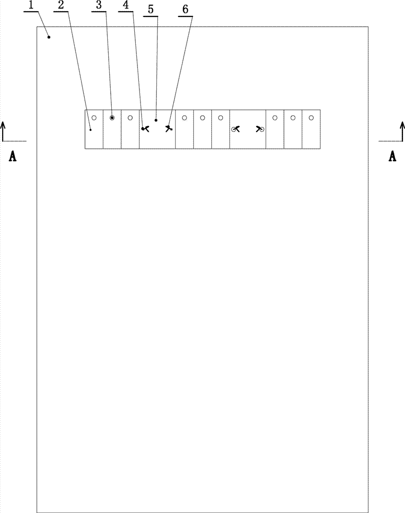
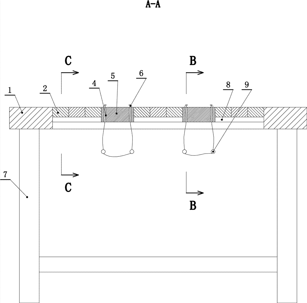
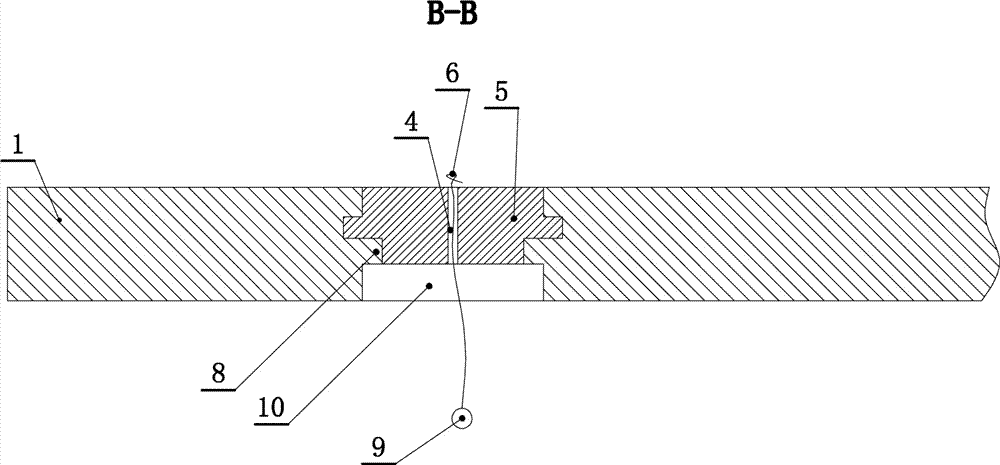
[0027] Such as Figure 1 to Figure 8 As shown, a restraint bed for an impatient patient includes a bed leg (7). The upper end of the bed leg (7) is fixedly connected with a bed board (1). The bed board (1) is characterized in that a left-right direction and an upward opening The board window (10), and the board window (10) are slidably connected with two symmetrical push-pull slides (5). The upper surface of the push-pull slide (5) is flush with the upper surface of the bed board (1). Each sliding slide plate (5) is provided with a pair of upper and lower perforated lace holes (4) corresponding to the left and right. The lace holes (4) are movably threaded with a lace (6), and the upper end of the lace (6) The upper end of ...


PUM


Abstract

The invention relates to a constraint bed for irritable patients. A placement plate window with the left-right moving direction and an upward opening is formed in the back portion of a bed board, twopush-pull sliding plates which are left and right symmetrically arranged are connected into the placement plate window in a left and right sliding mode, and the upper surfaces of the push-pull slidingplates are level with the upper surface of the bed board; a pair of transparent lace penetrating holes are left and right correspondingly formed in each push-pull sliding plate respectively, laces movably penetrate through the lace penetrating holes, and the upper ends of the laces penetrate through the upper ends of the lace penetrating holes; anti-disconnection buckles are arranged at the upperends of the laces, and anti-dropping hanging blocks are fixedly connected to the laces below the push-pull sliding plates. The front vertical wall and the back vertical wall of the placement plate window are outward sunken and communicated with sliding grooves which are horizontally formed respectively, sliding strips corresponding to the sliding grooves are fixedly connected to the front surfaces and the back surfaces of the push-pull sliding plates respectively, and the sliding strips are connected into the sliding grooves in a left and right sliding mode. Supporting strips are fixedly connected to the inner sides, of the front vertical wall and the back vertical wall of the placement plate window, on the lower sides of the sliding grooves, a plurality of movable cover plates are movably erected on the upper surfaces of front supporting strips and back supporting strips, and the upper surfaces of the movable cover plates are level with the upper surface of the bed board.

Description

Technical field [0001] The invention relates to a medical device, in particular to a restraint bed for impatient patients. Background technique [0002] The hospital bed is a medical device that can be used in all departments of the hospital. Under normal circumstances, the patient is lying in bed to treat the pain, but sometimes due to various reasons, the patient will be emotional and will not cooperate with the medical staff to treat it. Therefore, many people have to cooperate and press the feet and hands of the patient to perform infusion therapy. This operation is very troublesome, time-consuming and laborious, and increases the workload and difficulty of the medical staff. Summary of the invention [0003] In view of the shortcomings, the present invention provides a restraint bed for impatient patients that saves time and effort and can improve work efficiency. [0004] The technical solutions of the present invention to solve the above technical problems are as follows: [...

Claims


Application Information

Patent Timeline
Patent Type & Authority Applications(China)
IPC IPC(8): A61G7/00A61G7/05A61F5/37
Inventor 李泉山
Owner 李泉山
Learn More