A waste oil device

A technology of waste oil and grease, which is applied in the direction of recycling fat oil/fatty acid from waste, producing fat, and recycling fatty substances, etc. It can solve problems such as poor collection effect, doping of washing water and oil mixture, increased labor intensity and refining cost, etc. Achieve the effect of maintaining the original concentration, reducing labor intensity and reducing the cost of refining

Active Publication Date: 2018-11-13
天台县恒规环境科技有限公司
View PDF6 Cites 0 Cited by
  • Summary
  • Abstract
  • Description
  • Claims
  • Application Information

AI Technical Summary

Problems solved by technology

However, the existing waste oil is generally poured into the pouring tank and directly introduced into the sewage system, which makes it difficult to collect the waste oil, and the collection effect is poor. There are also some existing oil collection devices, but they are relatively The setting is too crude, and it is easy to mix the flushing water with the oil mixture when flushing the inverted irrigation tank, which greatly reduces the original purity of the oil mixture. Therefore, the labor intensity and refining cost will be greatly increased when the oil is refined in the later stage

Method used


Image

  • A waste oil device
  • A waste oil device
  • A waste oil device

Examples


Embodiment Construction

[0018] All features disclosed in this specification, or steps in all methods or processes disclosed, may be combined in any manner, except for mutually exclusive features and / or steps.

[0019] Any feature disclosed in this specification (including any appended claims, abstract and drawings), unless expressly stated otherwise, may be replaced by alternative features which are equivalent or serve a similar purpose. That is, unless expressly stated otherwise, each feature is one example only of a series of equivalent or similar features.

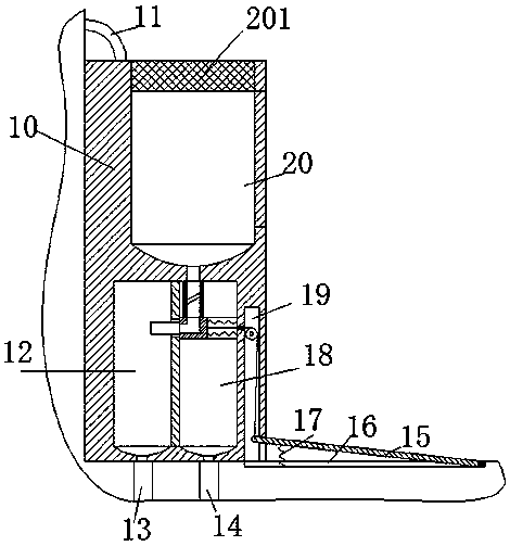
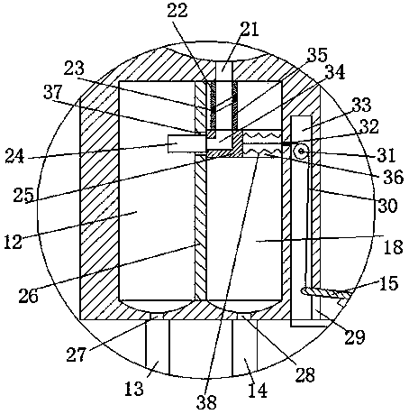
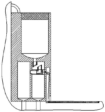
[0020] Such as Figure 1 to Figure 4 As shown, a waste grease device of the device of the present invention includes a pouring box 10 fixedly installed on the ground and close to the wall, and the pouring box 10 includes a pouring cavity 20 at the upper end and a guiding cavity at the lower end, and the pouring cavity 20 is provided with an upward pouring port, and a filter screen 201 is fixed in the pouring port, and the larger pollution par...


PUM


Abstract

The invention discloses a waste grease device which comprises a backward flow tank, wherein the backward flow tank is fixedly mounted on the ground and tightly adhered to a wall body; the backward flow tank comprises a backward flow cavity in an upper end and a guide cavity in a lower end; a backward flow hole which is opened upwards is formed in the backward flow cavity; a filtering net is fixedly arranged in the backward flow hole; a partition plate which extends up and down is fixedly mounted in the middle of the guide cavity; the guide cavity is partitioned into a discharge groove in a left side and a grease groove in a right side by the partition plate; a cleaning tube communicated with the backward flow cavity is arranged at the upper end of the backward flow tank; an opening and closing device for controlling the effluent of the cleaning tube is further mounted on the wall body; a first communicating groove is formed between the backward flow cavity and the grease groove; an upper tube sleeve is fixedly mounted at the lower end of the first communicating groove; a first through groove which is communicated with the first communicating groove is formed in the upper tube sleeve; a sliding groove which extends leftwards and rightwards is formed in the grease groove; a second through groove which is communicated with a discharge groove and the grease groove is formed in thepartition plate; a sliding connection block is mounted in the sliding groove in a left and right sliding connection manner; a right angle groove is formed in the sliding connection block.

Description

technical field [0001] The invention relates to the field of oil processing, in particular to a waste oil device. Background technique [0002] The recycling of waste oil is extremely widespread in real life, and it is often reprocessed into a series of products such as chemical raw materials and soap. However, the existing waste oil is generally poured into the pouring tank and directly introduced into the sewage system, which makes it difficult to collect the waste oil, and the collection effect is poor. The setting is too simple, and it is easy to mix the flushing water with the oil mixture when flushing the pouring pool, which greatly reduces the original purity of the oil mixture, so the labor intensity and refining cost will be greatly increased in the later stage of refining oil. Contents of the invention [0003] Aiming at the deficiencies of the above-mentioned technologies, the present invention proposes a waste grease device. [0004] A waste grease device of ...

Claims


Application Information

Patent Timeline
IPC IPC(8): C11B13/00
CPCY02W30/74
Inventor 何金英
Owner 天台县恒规环境科技有限公司
Why Eureka
Try Eureka