
Pixel structure, display panel and display device

A technology of pixel structure and display panel, used in static indicators, instruments, nonlinear optics, etc., can solve the problems of reducing display effect and aliasing phenomenon.

Active Publication Date: 2018-01-16
BOE TECH GRP CO LTD +1
View PDF6 Cites 14 Cited by
  • Summary
  • Abstract
  • Description
  • Claims
  • Application Information

AI Technical Summary

Problems solved by technology

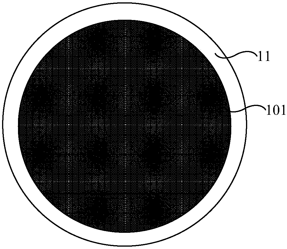
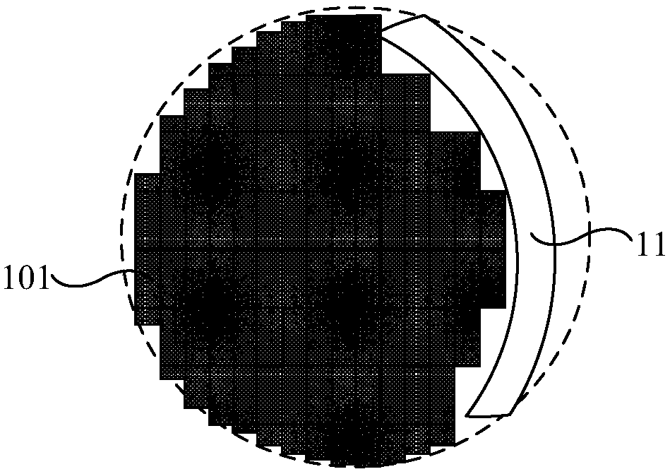
However, in this way, since the sub-pixel 101 is a rectangle, there will be a jagged phenomenon around the display area during the display process, thereby reducing the display effect.

Method used


Image

  • Pixel structure, display panel and display device
  • Pixel structure, display panel and display device
  • Pixel structure, display panel and display device

Examples


Embodiment Construction

[0032] The following will clearly and completely describe the technical solutions in the embodiments of the present invention with reference to the accompanying drawings in the embodiments of the present invention. Obviously, the described embodiments are only some, not all, embodiments of the present invention. Based on the embodiments of the present invention, all other embodiments obtained by persons of ordinary skill in the art without making creative efforts belong to the protection scope of the present invention.

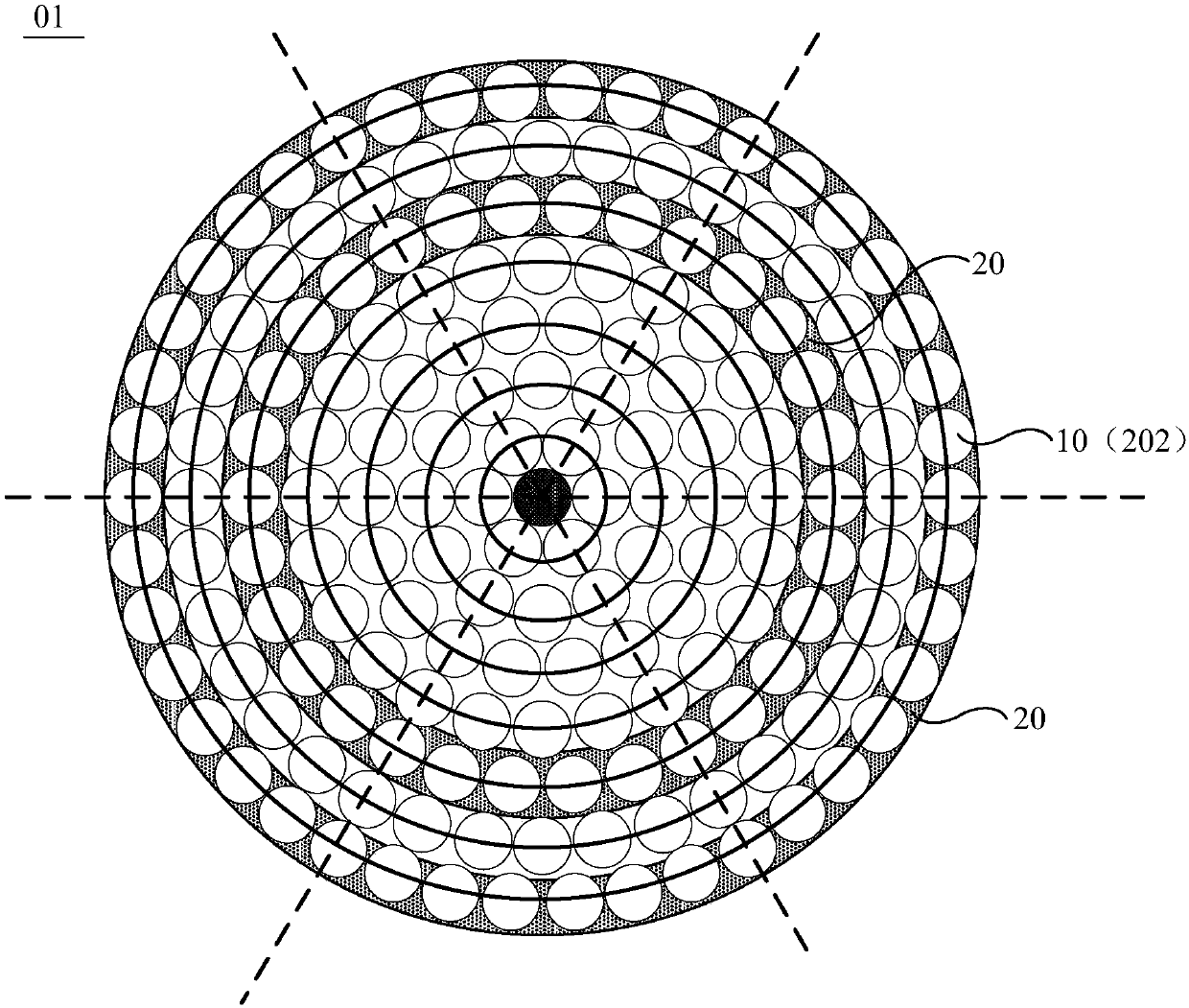
[0033] An embodiment of the present invention provides a pixel structure 01, such as figure 2 As shown, a plurality of circular pixels 10 are included. Wherein, the plurality of circular pixels 10 includes a central pixel 201 and a plurality of peripheral pixels 202 . A plurality of peripheral pixels 202 are distributed around the central pixel 201 .

[0034] The plurality of surrounding pixels 202 constitute a plurality of first pixel groups 20 . Specific...


PUM

PropertyMeasurementUnit
Angleaaaaaaaaaa

Abstract

The embodiment of the invention relates to the technical field of display, and provides a pixel structure, a display panel and a display device for weakening jaggies at the periphery of a display area. The pixel structure comprises multiple circular pixels; the circular pixels include one center pixel and multiple peripheral pixels; the peripheral pixels form multiple first pixel groups; multipleperipheral pixels in each first pixel group are distributed on the same circumference with the center pixel as the circle center; in the direction away from the center pixel, the radii of the circumferences where the peripheral pixels in different first pixel groups are distributed are gradually increased. The pixel structure is used for displaying images.

Description

technical field [0001] The present invention relates to the field of display technology, in particular to a pixel structure, a display panel and a display device. Background technique [0002] With the continuous development of display technology, display devices are more and more widely used in the field of smart wearables. In some smart wearable products, such as smart watches, smart glasses, etc., in order to meet the design of smart wearable products and consider ergonomics and convenience, the display area in smart wearable products, such as Figure 1a As shown, a circle is usually used. [0003] However, in the prior art, the sub-pixels 101 on the display panel are rectangular. In this case, when the area of ​​the circular display area surrounded by the frame 11 is smaller than the area of ​​the display panel, part of the sub-pixels 101 located at the edge are covered by the frame 11. block. In this way, the areas of the red sub-pixel 101 , the green sub-pixel 101 an...

Claims


Application Information

Patent Timeline
IPC IPC(8): G02F1/1343
CPCG09G3/2003G09G2300/0426G09G2300/0452
Inventor 陈仕琦姜妮石博邓银
Owner BOE TECH GRP CO LTD
Learn More