
Hardware perforating mechanism provided with material receiving tank

A receiving trough and hardware technology, applied in leather punching/punching/cutting, metal processing, small raw leather/big raw leather/leather/fur mechanical treatment, etc., can solve the problem of low punching efficiency, slow effect, and punching The edge is not necessarily uniform and other problems, to achieve the effect of good punching effect and high efficiency

Inactive Publication Date: 2018-01-19
DONGGUAN LIANZHOU INTPROP OPERATION MANAGEMENT CO LTD
View PDF5 Cites 10 Cited by
  • Summary
  • Abstract
  • Description
  • Claims
  • Application Information

AI Technical Summary

Problems solved by technology

[0002] When the existing leather or cloth parts generally need to be punched, the existing method is to punch holes manually, the punching efficiency is low, the effect is slow, and the edge of the punching place is not necessarily uniform, and the effect is limited

Method used


Image

  • Hardware perforating mechanism provided with material receiving tank

Examples


Embodiment Construction

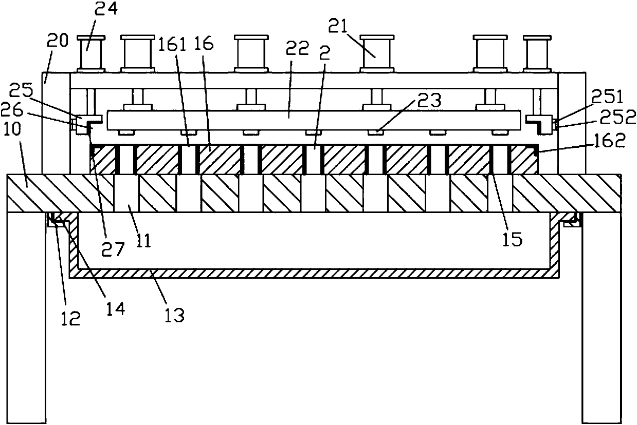
[0013] Example, see figure 1 As shown, a hardware punching mechanism with a material receiving tank includes a frame 10, the top surface of the top plate of the frame 10 is fixed with an upper support frame 20, and the top surface of the middle of the top plate of the frame 10 is fixed with The top surface of the lower mold block 16 has a plurality of positioning punching through holes 161, the top surface of the top plate of the upper support frame 20 is fixed with a plurality of punching cylinders 21, and the push rod of the punching cylinder 21 passes through the upper support frame 20 The top plate is fixed on the top surface of the upper pressure block 22, and the bottom surface of the upper pressure block 22 has a plurality of punches 23 corresponding to the positioning punching through holes 161;

[0014] The top plate of the frame 10 has a blanking through hole 11 corresponding to the positioning punching through hole 161, the bottom surface of the top plate of the frame ...


PUM


Abstract

The invention discloses a hardware perforating mechanism provided with a material receiving tank. The mechanism comprises a rack. An upper supporting frame is fixed to the top surface of a top plate of the rack. A lower die block is fixed to the top surface of the middle of the top plate of the rack. A plurality of positioning and stamping through holes are formed in the top surface of the lower die block. A plurality of stamping oil cylinders are fixed to the top surface of a top plate of the upper supporting frame. Push rods of the stamping oil cylinders penetrate through the top plate of the upper supporting frame to be fixed to the top surface of an upper pressing block. The bottom surface of the upper pressing block is provided with a plurality of puncher pins corresponding to the positioning and stamping through holes. The top plate of the rack is provided with discharging through holes corresponding to the positioning and stamping through holes. Side guide bent blocks are fixedto the two sides of the bottom surface of the top plate of the rack. Bent extension sides are arranged on the two sides of the material receiving tank and are inserted into and sleeved with positioning inserting grooves formed between the side guide bent blocks and the bottom surface of the top plate of the rack. The discharging through holes face the material receiving tank. The hardware perforating mechanism provided by the invention can be used for perforating a plurality of holes at a time, and is good in perforating effect and high in efficiency.

Description

Technical field: [0001] The invention relates to the technical field of hardware equipment, and more specifically to a hardware punching mechanism with a material receiving tank. Background technique: [0002] When the existing leather or cloth body generally needs to be perforated, the existing method is manual perforation, which has low perforation efficiency and slow effect, and the edge of the perforation is not necessarily uniform, and the effect is limited. Summary of the invention: [0003] The purpose of the present invention is to overcome the shortcomings of the prior art and provide a hardware punching mechanism with a material receiving trough body, which can perform multiple punching at a time, has good punching effect and high efficiency. [0004] The solution of the present invention to solve the technical problem is: [0005] A hardware punching mechanism with a material receiving trough includes a frame. The top surface of the top plate of the frame is fixed with an ...

Claims


Application Information

Patent Timeline
IPC IPC(8): B26F1/02B26F1/14B26D7/18C14B5/00
Inventor 杨勇
Owner DONGGUAN LIANZHOU INTPROP OPERATION MANAGEMENT CO LTD
Learn More