Numerically-controlled cutting machine capable of realizing rotating punching and punching method thereof

A cutting machine and blanking technology, applied in conveyors, metal processing, coiling strips, etc., can solve the problems of low precision control of punching height, inability to automatically adjust control, inconvenient punching adjustment, etc., to achieve punching The cutting effect is good, the interval is reasonable, and the replacement is convenient

Active Publication Date: 2016-11-23
QUZHOU TAIWEI PRECISE MASCH CO LTD
View PDF11 Cites 7 Cited by
  • Summary
  • Abstract
  • Description
  • Claims
  • Application Information

AI Technical Summary

Problems solved by technology

[0002] The CNC cutting machine needs to punch continuously. The cutting machine of the prior art is inconvenient to adjust the punching, and the control precision of the punching height is not high, which easily leads to incomplete punching and adhesion of the leather surface; The head of the machine is fixed and cannot be rotated, resulting in more blanks on the ingredients
The existing technology has a low degree of intelligent automation and cannot automatically adjust the control

Method used


Image

  • Numerically-controlled cutting machine capable of realizing rotating punching and punching method thereof
  • Numerically-controlled cutting machine capable of realizing rotating punching and punching method thereof
  • Numerically-controlled cutting machine capable of realizing rotating punching and punching method thereof

Examples


Embodiment 1

[0068] In this embodiment, the structure of the invention is described in detail with reference to the drawings.

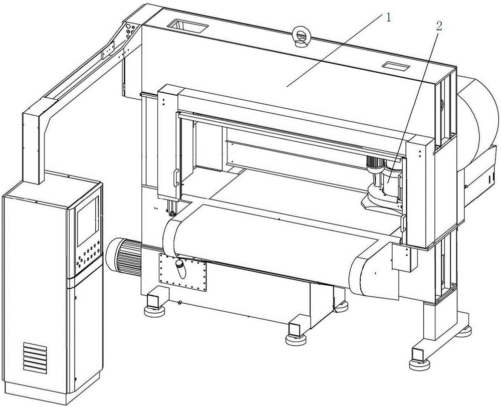
[0069] As shown in the figure, the rotary punching CNC cutting machine includes a gantry body 1 and a controller of the CNC cutting machine. The body is equipped with a rotary punching device, an automatic belt deviation correction device, a feeding device, a hydraulic device, and a synchronous reduction device;

[0070] The body 1 is provided with a rotary punching device 2, which includes:

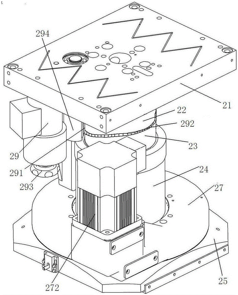
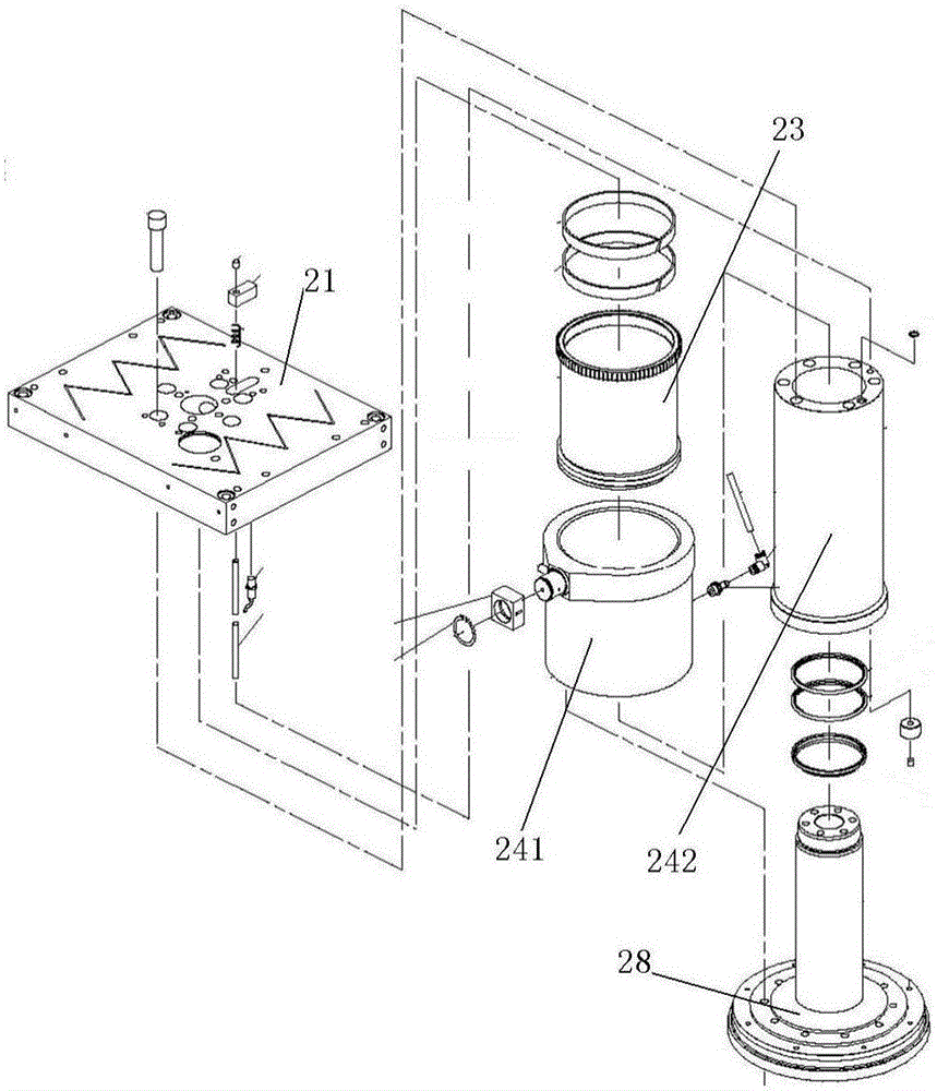
[0071] Horizontal mobile platform 21, which can move horizontally is located on the body 1;

[0072] The punching mechanism includes a cylinder 22 arranged on a horizontal moving table 21. The lower end of the cylinder 22 can be raised and lowered with a rotating cylinder liner 23. The outer wall of the lower end of the rotating cylinder liner 23 is connected to the inner wall of the oil cylinder 24 through threads and drives the oil cylinder 24. , the cylinder 22, the rota...

Embodiment 2

[0084] With reference to Embodiment 1, the feeding device includes a belt-drawing mechanism, a belt-pressing mechanism, and a feeding mechanism.

[0085] The drawstring mechanism includes an endless drawstring 33 that moves counterclockwise. The pull belt mechanism includes a first pull pulley 331 and a second pull pulley 332 horizontally arranged on the inside of the drawstring 33, and a third pull pulley 333 is also arranged below the first pull pulley 331 and the second pull pulley 332 .

[0086] A belt pressing mechanism, which includes a first pressing roller 35 that presses the blank 34 to be cut on the draw belt 33 and moves clockwise;

[0087] Feeding mechanism, it comprises movable feeding car 36, is provided with a plurality of front drums 38 and rear drums 39 for placing blank 34 on the feeding car 36, and the front end of feeding car 36 is also provided with to be used for blank 34 preliminary Gather up the compacted second compaction roller 310 or compaction whe...

Embodiment 3

[0095] In combination with Embodiment 1, the CNC cutting machine is provided with an automatic belt deviation correction device, which includes an offset detection mechanism 44, an offset correction mechanism 45, and a controller 47; the deviation correction detection mechanism 44 is arranged on both sides of the belt 43, including rolling elements 441, the rolling parts are bearings or rollers. Other circular moving objects can also be used, so that the contact between the offset detection mechanism 44 and the belt 43 is a sliding contact, which reduces friction and makes the belt move more smoothly without jamming. The top of the correction detection mechanism is also provided with a belt positioning groove plate 46, one side of which is provided with a through groove 461 for the belt to pass through, and the other side is provided with a mounting hole 462 for installing the rolling element and the turret, and the mounting hole 462 is connected with the through groove. 461 i...


PUM


Abstract

The invention discloses a numerically-controlled cutting machine capable of realizing rotating punching. The machine comprises a rotating punching device, an automatic belt deviation correcting device, a feeding device, a hydraulic device, a synchronous speed reduction device, a horizontal moving table, a punching mechanism, a rotating mechanism and a travel adjusting mechanism, wherein the punching mechanism comprises a cylinder barrel, a rotating cylinder sleeve, an oil cylinder and a piston assembly; the rotating mechanism comprises a suspending plate with a tool arranged at the bottom; a protecting cover is rotationally connected; and the travel adjusting mechanism comprises a double-end motor, a gear shaft and a fine-adjustment handle. According to the machine, a combined oil cylinder assembly and the combined piston assembly are arranged, the punching reaction speed is high, the punching pressure is high, and the punching effect is good; the travel adjusting mechanism is arranged, the punching travel can be adjusted rapidly by the aid of the double-end motor, the double-end motor can be rotated manually while change, and ultra-high-precision fine travel adjustment is realized; and the rotatable rotating mechanism is arranged, the tool is convenient to replace, and meanwhile, the utilization rate of materials can be greatly increased.

Description

technical field [0001] The invention relates to the technical field of numerical control cutting machines, in particular to a rotary punching numerical control cutting machine. Background technique [0002] The CNC cutting machine needs to punch continuously. The cutting machine of the prior art is inconvenient to adjust the punching, and the control precision of the punching height is not high, which easily leads to incomplete punching and adhesion of the leather surface; The head of the machine is fixed and cannot be rotated, resulting in more blanks on the ingredients. The prior art has a low degree of intelligent automation and cannot automatically adjust and control. Contents of the invention [0003] In view of the above problems, the invention provides a rotary punching CNC cutting machine. [0004] The first object of the present invention is to provide a rotary punching CNC cutting machine, including a gantry-type body and a controller of the CNC cutting machine...

Claims


Application Information

Patent Timeline
Patent Type & Authority Applications(China)
IPC IPC(8): B26F1/40B26F1/44B26D7/02B26D7/26B65H23/038B65G15/64
CPCB26D7/02B26D7/2628B26F1/40B26F1/44B65G15/64B65H23/038
Inventor 童孝忠
Owner QUZHOU TAIWEI PRECISE MASCH CO LTD
Why Eureka
Try Eureka