Enclosing structure capable of inhibiting vortex-induced vibration and method for inhibiting vortex-induced vibration

A technology of enclosure structure and vortex-induced vibration, which is applied in the direction of engine function, vibration suppression adjustment, installation/support configuration of wind turbine, etc. It can solve the problems of reduced significance, difficulty in adapting to changes in wind speed, and corresponding to different wind speeds

Active Publication Date: 2018-01-19
BEIJING GOLDWIND SCI & CREATION WINDPOWER EQUIP CO LTD
View PDF5 Cites 10 Cited by
  • Summary
  • Abstract
  • Description
  • Claims
  • Application Information

AI Technical Summary

Problems solved by technology

[0032] The installation helix 10a (or spiral plate) is only used in the hoisting stage, which reduces the significance and loses a lot. Considering the long-term operation and use, it is difficult to adap

Method used


Image

  • Enclosing structure capable of inhibiting vortex-induced vibration and method for inhibiting vortex-induced vibration
  • Enclosing structure capable of inhibiting vortex-induced vibration and method for inhibiting vortex-induced vibration
  • Enclosing structure capable of inhibiting vortex-induced vibration and method for inhibiting vortex-induced vibration

Examples


Embodiment Construction

[0086] In order to enable those skilled in the art to better understand the technical solutions of the present invention, the present invention will be further described in detail below in conjunction with the accompanying drawings and specific embodiments.

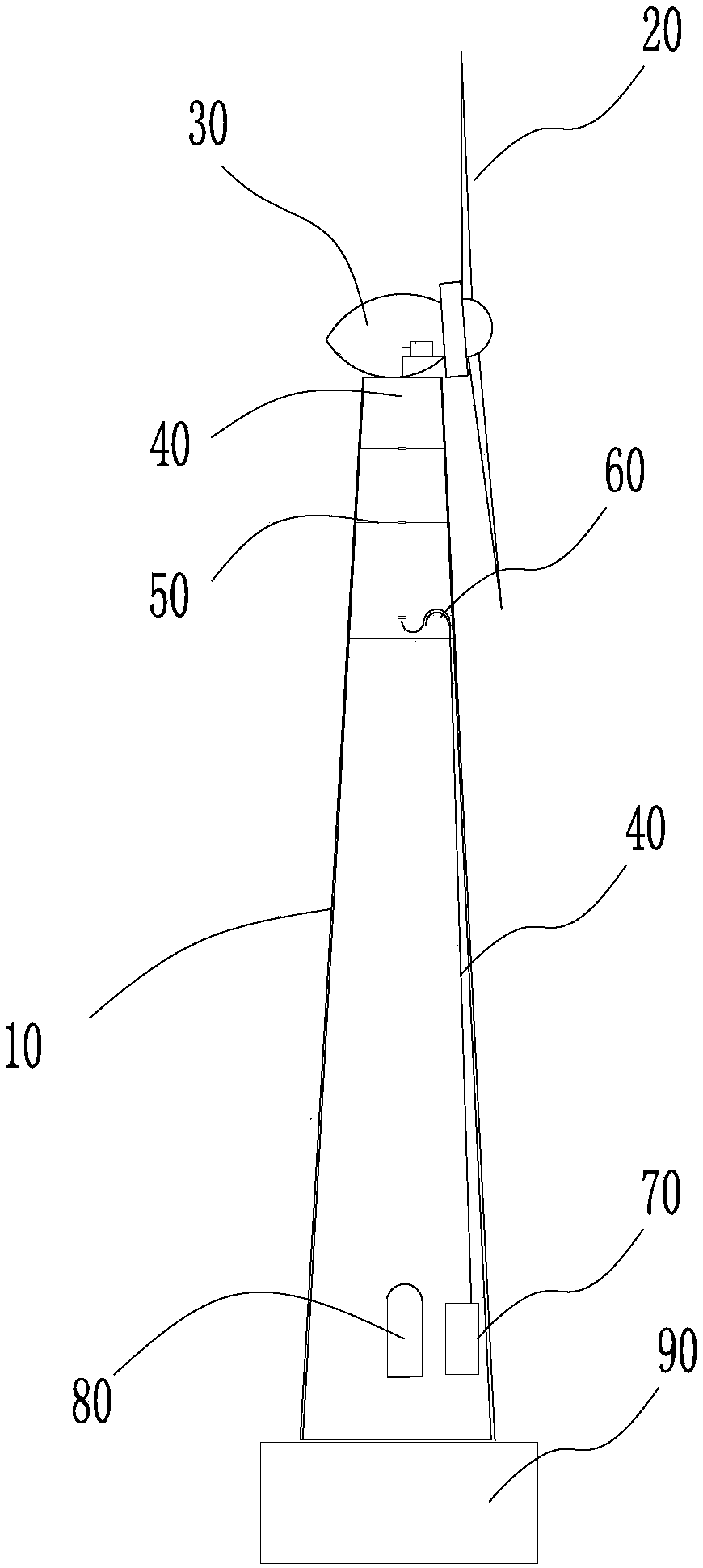
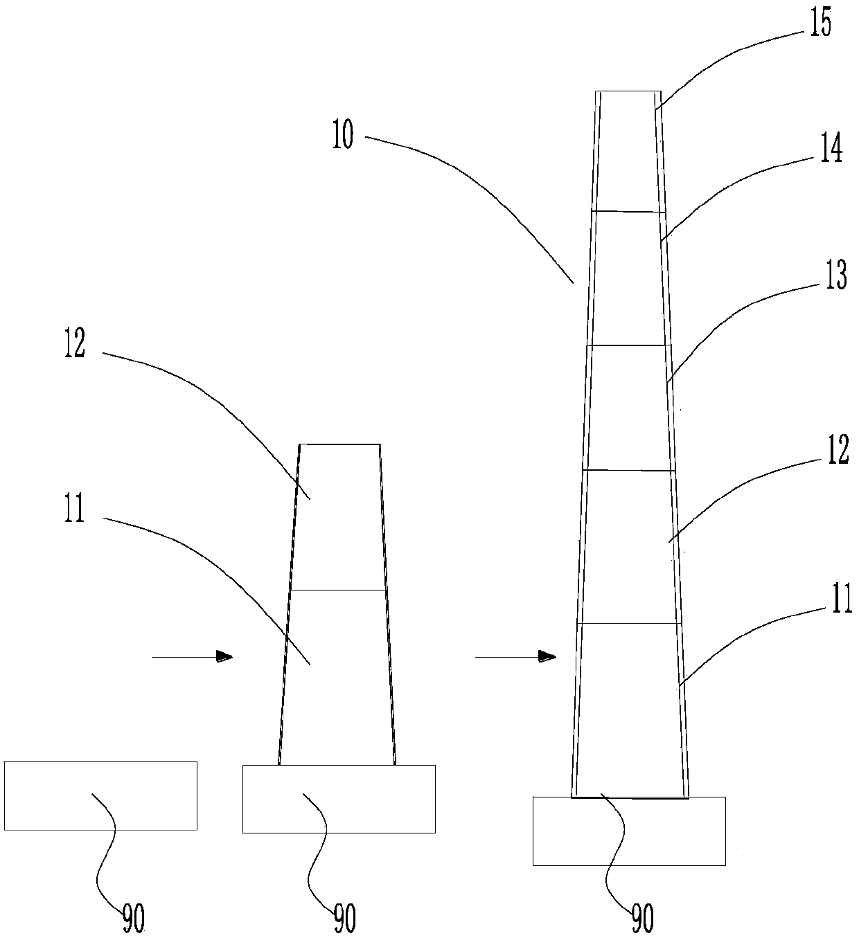
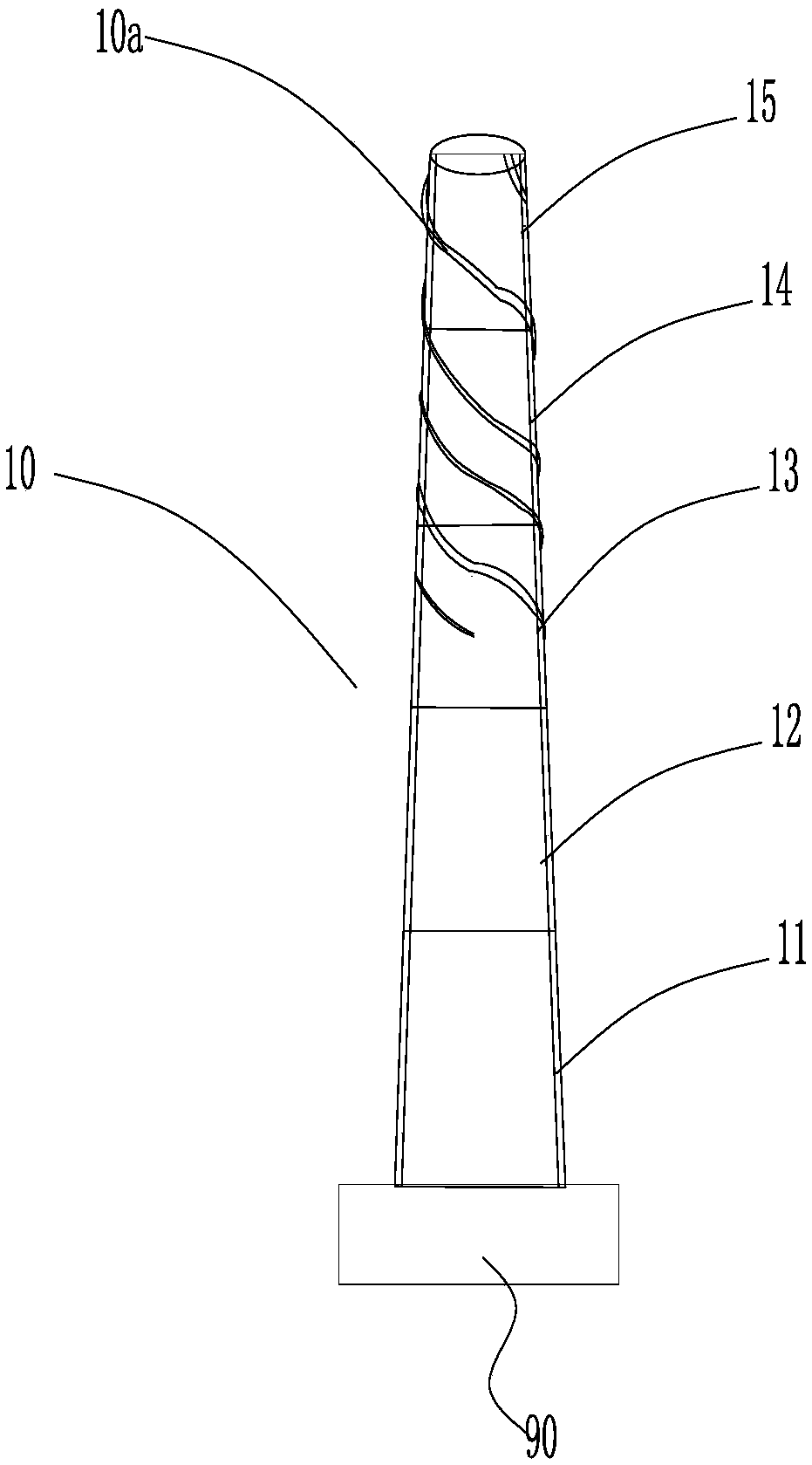
[0087] Please refer to Figure 4 , Figure 4 It is a structural schematic diagram of a specific embodiment of the tower with the function of suppressing vortex-induced vibration provided by the present invention; Figure 5 for Figure 4 Schematic diagram of the expansion of the upper part of the tower with the suction through hole.

[0088] like Figure 4 As shown, the tower 100 is arranged on the tower foundation 600, and the engine room 200, the generator 300, the impeller 400 and other components are installed on the top of the tower 100. like Figure 5As shown, in this embodiment, on the upper part of the tower 100, a number of suction through-holes 100a penetrating the inner and outer walls of the tower 100 are ...


PUM

PropertyMeasurementUnit
The inside diameter ofaaaaaaaaaa

Abstract

The invention discloses an enclosing structure capable of inhibiting vortex-induced vibration and a method for inhibiting vortex-induced vibration. The enclosing structure is provided with suction through holes, wherein the suction through holes penetrate the circumferential wall of the enclosing structure and are formed in the circumferential direction of the enclosing structure. The enclosing structure is further provided with suction equipment. By means of the suction equipment, suction can be conducted on the suction through holes from outside to inside so that a boundary layer on the outer surface of the enclosing structure can be inhibited from breaking away from the outer surface. The boundary layer can be adsorbed to the outer surface of a tower barrel by way of suction, and thus the boundary layer is inhibited or directly stopped from breaking away from the outer surface of the tower barrel; and formation causes of vortex-induced vibration are reduced or eliminated. In addition, in the suction process, suction force adjustment can be conducted at any time according to the vibration state, and high flexibility is achieved; furthermore, noise can be obviously and remarkablylowered through suction conducted on the suction through holes; no matter during the unit hoisting period or during the operation period, the suction mode can play a role in inhibiting vortex-inducedvibration all the time; and when inward discharging is conducted, the interior of the tower barrel can be cooled.

Description

technical field [0001] The invention relates to the technical field of enclosure structures, in particular to an enclosure structure capable of suppressing vortex-induced vibration and a method for suppressing vortex-induced vibration. Background technique [0002] Please refer to Picture 1-1 , Picture 1-1 Schematic diagram of wind power generation equipment. [0003] The foundation of the wind power generation equipment is the tower tube 10, which acts as a load bearing and protects the whole machine. As an example, taking a tower 10 with a circular cross section as an example, the tower 10 may be a steel cylinder, or a combination of a steel cylinder and a concrete tower. The tower 10 carries the nacelle 30 of the wind power generation equipment, the generator and the wind turbine 20 . The wind power generating set composed of the wind turbine 20 and the generator completes the task of obtaining wind energy and converting it into electrical energy. The converted elect...

Claims


Application Information

Patent Timeline
IPC IPC(8): F03D13/20F03D7/04F03D80/00
CPCF03D13/20F15D1/12F03D80/88Y02E10/72Y02E10/728F03D80/00E04H12/08E04H12/12F05B2220/30F05B2260/96F16F15/023F16F2222/126F16F2230/22F16F2230/36
Inventor 马盛骏
Owner BEIJING GOLDWIND SCI & CREATION WINDPOWER EQUIP CO LTD
Why Eureka
Try Eureka