
Expansion joint failure test method

A test method and technology of expansion joints, which can be used in the direction of measuring the acceleration and deceleration rate of fluids and using liquid/vacuum for liquid tightness measurement. The effect of ensuring measurement accuracy

Inactive Publication Date: 2018-04-27
WUXI YONGXING METAL HOSE
View PDF3 Cites 2 Cited by
  • Summary
  • Abstract
  • Description
  • Claims
  • Application Information

AI Technical Summary

Problems solved by technology

[0003] Most of the existing expansion joints are made of a single material, which has poor high temperature resistance and short service life
Some old-fashioned expansion joints still have defects such as air leakage, which poses a huge safety hazard to inspectors and the surrounding environment

Method used


Image

  • Expansion joint failure test method
  • Expansion joint failure test method

Examples


Embodiment Construction

[0027] The present invention will be further described below in conjunction with the accompanying drawings and embodiments.

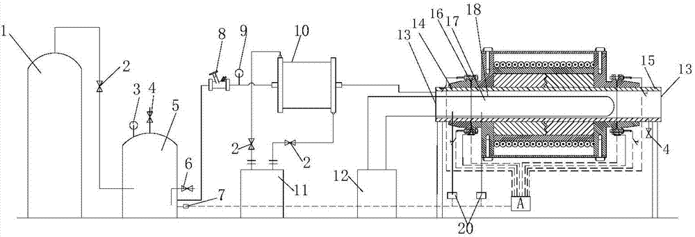
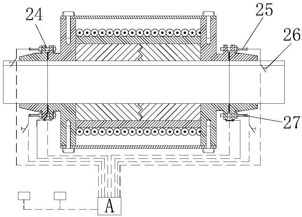
[0028] Such as figure 1 As shown, a failure test device of an expansion joint includes left and right pipes, the left pipe flange connected to the left pipe, the right pipe flange connected to the right pipe, and the left pipe flange connected by bolts and gaskets. The expansion joint between the flange and the right flange of the pipeline, wherein, the non-connecting ends of the left pipeline and the right pipeline are closed and a sealed cavity is formed inside, and a heating mechanism is provided inside the sealed cavity; There is a high-pressure gas storage tank, and the high-pressure gas storage tank is connected to the balance valve and the flow meter in turn through the pipeline and finally communicates with the sealed cavity. The test device also includes sensors for measuring the temperature and pressure inside the sealed cavity; the expansion ...


PUM


Abstract

The invention discloses an expansion joint failure test method, which is based on a test device. The device comprises a left pipeline and a right pipeline which are mutually connected, a pipeline leftflange and a pipeline right flange which connect the left pipeline and the right pipeline, and an expansion joint which is connected between the pipeline left flange and the pipeline right flange, wherein the non-connecting ends of the left pipeline and the right pipeline are both sealed, sealing cavities are formed inside, and the sealing cavity is internally provided with a heating mechanism; the sealing cavity is externally provided with a high-pressure gas storage tank; the high-pressure gas storage tank is sequentially connected with a balance valve and a flowmeter through the pipelinesand is finally communicated with the sealing cavity. The test device also comprises a sensor for measuring the temperature and the pressure inside the sealing cavity. Whether a leakage phenomenon exists in the expansion joint connection system can be detected, and the leakage rate of the expansion joint connection system can be calculated accurately.

Description

technical field [0001] The invention relates to a failure test method of an expansion joint. Background technique [0002] The expansion joint is a flexible structure arranged on the container shell or pipeline to compensate for the additional stress caused by temperature difference and mechanical vibration. Utilize the effective expansion and contraction deformation of the working body of the expansion joint to absorb the dimensional changes of pipelines, conduits, containers, etc. due to thermal expansion and contraction, or to compensate for the axial, lateral, and angular displacement of pipelines, conduits, containers, etc. Can be used for noise reduction and vibration reduction. Has been widely used in environmental protection, chemical industry, metallurgy and other fields. In the field of environmental protection, in order to prevent the pipe from being deformed or damaged due to thermal elongation or temperature stress when the heating pipe heats up, it is necessa...

Claims


Application Information

Patent Timeline
Patent Type & Authority Applications(China)
IPC IPC(8): G01M3/26
CPCG01M3/26
Inventor 王铮
Owner WUXI YONGXING METAL HOSE
Learn More