Cable trough and installing method thereof

A technology of cable trough and installation location, which is applied in the direction of electrical components, etc., which can solve problems such as the mismatch between the cover plate and the trough body, confusion in placement, and influence on the installation progress, and achieve the effect of clean installation site, reliable connection and convenient installation

Inactive Publication Date: 2018-01-19
江苏瑞仁汽车部件有限公司
View PDF14 Cites 0 Cited by
  • Summary
  • Abstract
  • Description
  • Claims
  • Application Information

AI Technical Summary

Problems solved by technology

Most of the existing cable troughs are composed of a trough body and a cover plate. During actual transportation and installation, the two materials are likely to cause confusion in placement, and the cover plate does not correspond to the trough body, which affects the installation progress.

Method used


Image

  • Cable trough and installing method thereof
  • Cable trough and installing method thereof

Examples


Embodiment Construction

[0020] In order to further explain the technical means and effects adopted by the present invention to achieve the intended invention purpose, the specific implementation, features and effects of the cable tray and its installation method proposed according to the present invention are described in detail below.

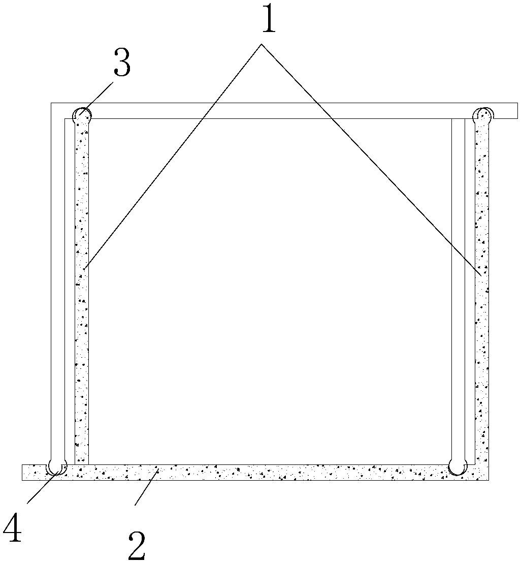
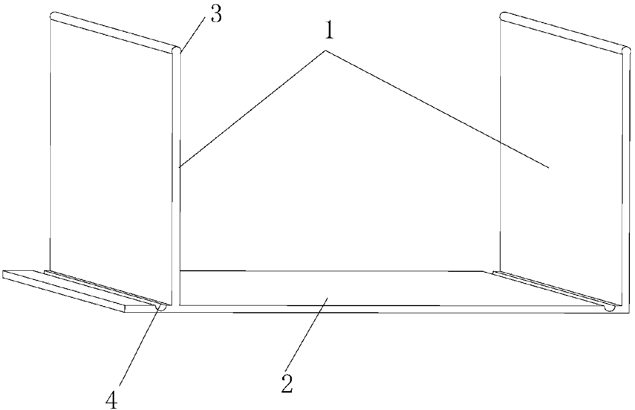
[0021] Such as figure 1 As shown, the present invention discloses a cable trough, which is formed by clamping two concave bottom frames, wherein the concave bottom frame includes two side plates 1 arranged in parallel and a bottom plate 2 connecting the two side plates 1, and the bottom plate One end of 2 is provided with an extension part;

[0022] The extension part and the interior of the bottom plate 2 are provided with locking grooves 3 corresponding to the protrusions 4 at the ends of the two side plates 1 of another concave chassis.

[0023] As a preferred technical solution, the card slot 3 is a circular card slot 3 , and the protrusion 4 is a circular protr...


PUM


Abstract

The invention discloses a cable trough which is formed by clamp-connecting two concave underframes. Each concave underframe comprises two parallelly arranged side plates and a base plate connected with the two side plates, wherein an external extending portion is arranged at one end of the base plate, and clamping grooves are formed in the external extending portion and the base plate and correspond to convex blocks at the ends of two side plates of the other concave underframe respectively. By adopting the technical scheme, the cable trough can have the advantages that the cable trough is formed by clamp-connecting the two concave underframes, and only one structure is needed on a construction site, so that an installing site is clean and tidy; in addition, the fabricated concave underframes are of mortise and tenon structures and are firm in connection and quick and convenient to install.

Description

technical field [0001] The invention relates to cable installation technology, in particular to a cable groove and an installation method thereof. Background technique [0002] Cable grooves are used to protect the cables inside for a longer life. Most of the existing cable ducts are composed of a duct body and a cover plate. During actual transportation and installation, the two materials are likely to cause confusion in placement, and the cover plate does not correspond to the duct body, which affects the installation progress. [0003] In view of the defects of the above-mentioned existing cable troughs, the inventor actively researches and innovates based on his rich practical experience and professional knowledge in the design and manufacture of such products for many years, and cooperates with the application of academic principles, in order to create a prefabricated cable trough And its installation method makes it more practical. Through continuous research, design...

Claims


Application Information

Patent Timeline
Patent Type & Authority Applications(China)
IPC IPC(8): H02G3/04
Inventor 梅仁平
Owner 江苏瑞仁汽车部件有限公司
Why Eureka
Try Eureka