LED light device

An LED lamp device and LED lamp technology, applied in lighting devices, lighting auxiliary devices, fixed lighting devices, etc., can solve the problems of inconvenient installation and disassembly of LED lamps, cumbersome installation operations, roof damage, etc., and increase the efficiency of disassembly and replacement. Avoid electric shock accidents and facilitate disassembly and replacement

Active Publication Date: 2018-10-16
DONGHAI JINGMING LIGHTING ELECTRICAL APPLIANCE CO LTD
View PDF5 Cites 0 Cited by
  • Summary
  • Abstract
  • Description
  • Claims
  • Application Information

AI Technical Summary

Problems solved by technology

[0002] LED lights generally use LED as the light source, and they are mostly installed on indoor roofs. LED lights are widely used because of their high luminous efficiency, low power consumption, long life, easy control, energy saving and environmental protection, etc., but the existing LED lights are in During installation, it is necessary to pre-embed bolts on the roof or fix them on the roof with expansion bolts. This installation method will not only cause damage to the roof, but also the installation operation is more cumbersome, which is not convenient for the rapid installation and disassembly of LED lights, and the existing LED lights When installing the lamp, first connect the wire to the LED lamp and then fix it after powering on. This installation method is likely to cause electric shock accidents.

Method used


Image

  • LED light device
  • LED light device
  • LED light device

Examples


Embodiment Construction

[0019] The preferred embodiments of the present invention will be described in detail below in conjunction with the accompanying drawings, so that the advantages and features of the present invention can be more easily understood by those skilled in the art, so as to define the protection scope of the present invention more clearly.

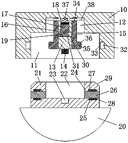
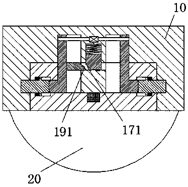
[0020] refer to Figure 1-3 The shown LED lamp device includes an LED lamp holder 10 installed on the roof and an LED lamp main body 20 for matching with the LED lamp holder 10 to connect and conduct electricity. The bottom surface of the LED lamp holder 10 is provided with There is a light trough 11 with an opening downward, a first sliding groove 12 is arranged in the top wall of the light trough 11, and two driving parts are arranged symmetrically in the first sliding groove 12, and each driving part includes The first sliding plate 34 extending downward into the lamp groove 11 and the outwardly pushing protrusion 35 arranged on the outer side...


PUM


Abstract

The invention discloses an LED lamp device. The LED lamp device comprises an LED lamp carrier base arranged in a roof, and an LED lamp main body connected with the LED lamp carrier base in a matched mode for electrification. The bottom end face of the LED lamp carrier base is provided with a lamp groove with an opening facing downwards. A first sliding groove is formed in the top end wall of the lamp groove. Two driving parts symmetrically arranged left and right are arranged in the first sliding groove. Each driving part comprises a first sliding plate extending into the lamp groove downwards, and a pushout protrusion arranged on the outer side of the bottom of the first sliding plate. The LED lamp device is simple in overall structure and safe and convenient to operate, the mounting, dismounting and replacing efficiencies of the LED lamp main body are improved, the shock accidents during mounting, dismounting and replacing of the LED lamp main body are effectively avoided, the life safety of personnel is ensured, and the LED lamp device is suitable for application and popularization.

Description

technical field [0001] The invention relates to the technical field of LED lamps, in particular to an LED lamp device. Background technique [0002] LED lights generally use LED as the light source, and they are mostly installed on indoor roofs. LED lights are widely used because of their high luminous efficiency, low power consumption, long life, easy control, energy saving and environmental protection, etc., but the existing LED lights are in During installation, it is necessary to pre-embed bolts on the roof or fix them on the roof with expansion bolts. This installation method will not only cause damage to the roof, but also the installation operation is cumbersome, which is not convenient for the rapid installation and disassembly of LED lights, and the existing LED lights When the lamp is installed, the wires are first connected to the LED lamp and then fixed after being energized. Such an installation method is likely to cause electric shock accidents. Contents of t...

Claims


Application Information

Patent Timeline
Patent Type & Authority Patents(China)
IPC IPC(8): F21S8/04F21V21/002F21V21/03F21V23/06F21Y115/10
Inventor 方民
Owner DONGHAI JINGMING LIGHTING ELECTRICAL APPLIANCE CO LTD
Why Eureka
Try Eureka