parallel switch

A technology of parallel connection and switching, which is applied in the direction of electric switches, electrical components, circuits, etc., and can solve problems such as potential safety hazards of drive shafts

Active Publication Date: 2020-10-20
SIEMENS AG
View PDF7 Cites 0 Cited by
  • Summary
  • Abstract
  • Description
  • Claims
  • Application Information

AI Technical Summary

Problems solved by technology

[0003] However, the parallel switch in the prior art has the following defects: since the contact modules between the two isolating switches are not connected, when the dynamic and static contacts of one of the contact modules are welded due to short circuit, the user will not know Under the circumstances, the driving shaft can still be operated to make it turn to the off position beyond the dead point, but at this time a certain contact module that is welded is still in the circuit-connected state, so the wrong indication of the driving shaft has a great impact on the entire power consumption. The system poses a security risk

Method used


Image

  • parallel switch
  • parallel switch
  • parallel switch

Examples


Embodiment Construction

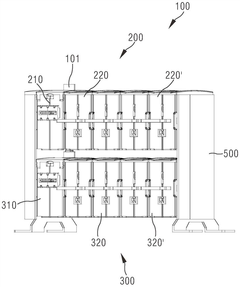
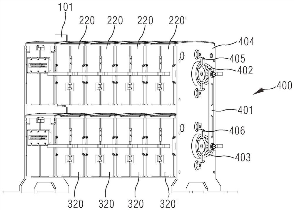
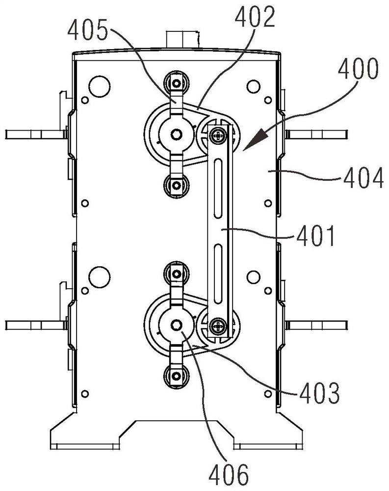
[0032] In order to have a clearer understanding of the technical features, purposes and effects of the invention, the specific implementation manners of the present invention will now be described with reference to the accompanying drawings, in which the same reference numerals represent the same parts.

[0033] In order to make the drawing concise, each drawing only schematically shows the parts related to the present invention, and they do not represent the actual structure of the product. In addition, to make the drawings concise and easy to understand, in some drawings, only one of the components having the same structure or function is schematically shown, or only one of them is marked.

[0034] Herein, "upper", "lower", "front", "rear", "left", "right", etc. are only used to indicate the positional relationship between related parts, not to limit their absolute positions.

[0035] In this document, "first", "second" and so on are only used to distinguish each other, but ...


PUM


Abstract

The present invention relates to a parallel switch. This parallel switch includes a first disconnecting switch and a second disconnecting switch which are stacked in a vertical direction; the first disconnecting switch is provided with a first driving module and at least one first contact module which are arranged side by side in a left-and-right direction; the second disconnecting switch is provided with a second driving module and at least one second contact module which are arranged side by side in a left-and-right direction; a connecting assembly is arranged between the first contact module located at the farthest end of the first driving module and the second contact module located at the farthest end of the second driving module; and the connecting assembly is connected with the mainshaft of the first contact module and the main shaft of the second contact module, so that synchronous action of the first contact module and the second contact module can be realized. The synchronism of the operation of the parallel switch is good. With the parallel switch adopted, a user can be prevented from performing misoperation when the contact modules are welded.

Description

technical field [0001] The invention relates to the field of electrical equipment, in particular to a parallel switch. Background technique [0002] The isolating switch is an electrical device commonly used in the circuit. It is used to change the circuit connection or isolate the circuit or equipment from the power supply. The contacts are contacted and separated, so as to control the closing or opening of the isolating switch, so as to realize the on-off control of the power supply line. In order to adapt to different power systems, two isolation switches can be connected in parallel up and down to form a parallel switch to cut off or connect two power sources at the same time. [0003] However, the parallel switch in the prior art has the following defects: since the contact modules between the two isolating switches are not connected, when the dynamic and static contacts of one of the contact modules are welded due to short circuit, the user will not know Under the ci...

Claims


Application Information

Patent Timeline
Patent Type & Authority Patents(China)
IPC IPC(8): H01H9/26
Inventor 宋建康周青山宋磊李棣楠约尔格·胡斯曼
Owner SIEMENS AG
Why Eureka
Try Eureka