LED dimming driving system

A technology of dimming drive and driving chip, applied in the field of drive system, can solve the problem of LED light source can not be dimmed, and achieve the effect of preventing stimulation, stabilizing brightness and ensuring stability

Inactive Publication Date: 2018-01-26
CHENGDU YUEXIANGXIANG TECH CO LTD
View PDF0 Cites 0 Cited by
  • Summary
  • Abstract
  • Description
  • Claims
  • Application Information

AI Technical Summary

Problems solved by technology

[0003] The purpose of the present invention is to overcome the defect that most of the LED light sources in the current market cannot be dimmed, and to provide an LED dimming drive system that not only has a simple structure, but also can be dimmed to meet people's individual needs.

Method used


Image

  • LED dimming driving system
  • LED dimming driving system

Examples


Embodiment

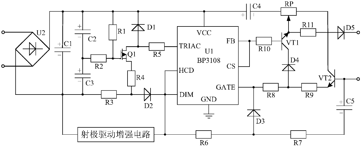
[0017] Such as figure 1 As shown, the LED dimming drive system of the present invention is mainly composed of a drive chip U1, a resistor R5, a resistor R6, a capacitor C4, a diode D1, a diode D3, a field effect tube power supply circuit, an emitter drive enhancement circuit and a triode drive circuit. Specifically, the P pole of the diode D1 is connected to the TRIAC pin of the driver chip U1 through the resistor R5, and its N pole is connected to the VCC pin of the driver chip U1. The FET power supply circuit is respectively connected to the P pole of the diode D1 and the DIM pin of the driving chip U1. The P pole of the diode D3 is connected to the DIM pin of the driver chip U1 through the resistor R6, and the N pole of the diode D3 is connected to the GATE pin of the driver chip U1. The triode drive circuit is connected to the P pole and N pole of the diode D3 and the FB pin of the drive chip U1 respectively. The anode of the capacitor C4 is connected to the VCC pin of t...


PUM


Abstract

The invention discloses an LED dimming driving system. The LED dimming driving system is characterized in that the LED dimming driving system is mainly formed by a drive chip U1, a resistor R5, a resistor R6, a capacitor C4, a diode D1, a diode D3, a field effect transistor power supply circuit, an emitter driving enhancing circuit and a triode drive circuit. The LED dimming driving system utilizes a BP3108 integrated chip to combine with the peripheral circuit, and can control resistance change of a slide rheostat RP so as to adjusting the luminance of the LED light source according to usingrequirements to satisfy the individual demand of people, thus being suitable for promotion and application.

Description

technical field [0001] The invention relates to a driving system, in particular to an LED dimming driving system. Background technique [0002] With the development of society and the improvement of living standards, people's minds have also been fully liberated. Nowadays, people are very individualized, have their own unique insights into the cognition of objects, and have different needs for things. Similarly, the sensitivity to light is not necessarily the same. Moreover, due to the increasing abundance of electronic products, people's excessive eye use is becoming more and more serious, and the degree of damage to the eyes is different, and the sensitivity to light is also different. Most of the LED light sources currently on the market cannot be dimmed, so they cannot meet people's individual needs. Contents of the invention [0003] The purpose of the present invention is to overcome the defect that most LED light sources in the market cannot be dimmed, and provide...

Claims


Application Information

Patent Timeline
Patent Type & Authority Applications(China)
IPC IPC(8): H05B33/08H05B44/00
Inventor 王青松
Owner CHENGDU YUEXIANGXIANG TECH CO LTD
Why Eureka
Try Eureka