Special tamping device for slope surface

A tamping device and slope surface technology, which is applied in the fields of soil protection, construction, infrastructure engineering, etc., can solve the problems of inability to tamp the slope surface, increase the working time, increase the economic cost, etc., and achieve simple structure and reduce work The effect of saving time and reducing economic costs

Inactive Publication Date: 2018-01-30
毛林杰
View PDF7 Cites 1 Cited by
  • Summary
  • Abstract
  • Description
  • Claims
  • Application Information

AI Technical Summary

Problems solved by technology

[0002] Most of the existing tamping machines are large-scale tamping equipment, and the cost investment is high. Although there are small tamping equipment, the tamping effect is poor, and the existing tamping equipment cannot realize the tamping work on the slope surface
In the process of highway repair construction, a compactor is required to compact the slope of the roadbed to ensure the stability of the roadbed and improve the service life of the roadbed. The traditional compaction of the slope of the roadbed still needs to be done manually, which is time-consuming and laborious. , the efficiency is not high, the quality of tamping is poor, the working time is increased, the economic cost is increased, and the normal construction period is delayed

Method used


Image

  • Special tamping device for slope surface
  • Special tamping device for slope surface
  • Special tamping device for slope surface

Examples


Embodiment Construction

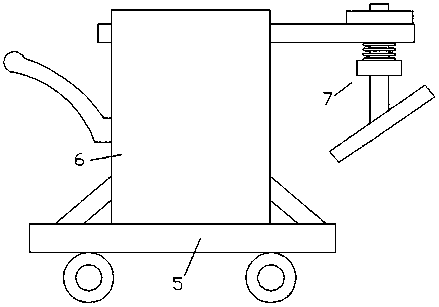
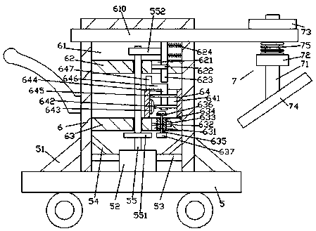
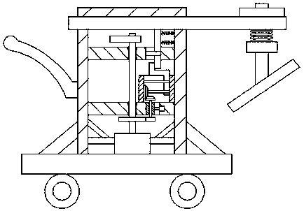
[0021] Such as figure 1 — Figure 4 As shown, a special tamping device for a slope surface of the present invention includes a mobile body 5 and a tamping body 6 fixedly installed on the top of the mobile body 5 , the tamping body 6 is provided with a The placement chamber 61 on the end face, the first crossbeam 62 and the second crossbeam 63 extending left and right are symmetrically arranged inside the placement chamber 61, and the extension ends on the left and right sides of the first crossbeam 62 and the second crossbeam 63 are respectively connected with The inner walls of the left and right sides of the placement chamber 61 are fixedly connected, and the top end surface of the mobile vehicle body 5 at the bottom of the placement chamber 61 is fixedly provided with a first motor 52 extending into the placement chamber 61. The first motor 52 The top is connected with the first rotating shaft 55 extending upwards, and the top extension of the first rotating shaft 55 runs ...


PUM


Abstract

The invention discloses a special tamping device for a slope surface, which comprises a mobile car body and a tamping body fixedly installed on the top of the mobile car body. The tamping body is provided with a placement cavity that runs through the bottom end surface of the tamping body. The extended first crossbeam and the second crossbeam, the extension ends on the left and right sides of the first crossbeam and the second crossbeam are respectively fixedly connected with the inner walls on the left and right sides of the placement chamber, and the top end surface of the mobile car body at the bottom of the placement chamber is fixedly provided with a Inside the first motor, the top of the first motor is connected with the first rotating shaft extending upwards, and the extension section of the top of the first rotating shaft runs through the second beam and the first beam in turn from bottom to top and is rotationally connected. The first rotating shaft The end of the top extension extends into the placement cavity above the top of the first crossbeam, and the outer surface of the first rotating shaft above the top of the first crossbeam is fixed with a top pressure eccentric wheel in the circumferential direction; the invention has simple structure, convenient operation, high compaction efficiency, and High quality reduces working time.

Description

technical field [0001] The invention relates to the technical field of construction equipment, in particular to a special compacting device for slope surfaces. Background technique [0002] Existing compacting machines are mostly large-scale compacting equipment, and the cost investment is relatively high. Although there are small-scale compacting equipment, the compacting effect is poor, and the existing compacting equipment cannot realize the compaction work of the slope surface. In the process of highway repair construction, a compactor is required to compact the slope of the roadbed to ensure the stability of the roadbed and improve the service life of the roadbed. The traditional compaction of the slope of the roadbed still needs to be done manually, which is time-consuming and laborious. , the efficiency is not high, the quality of tamping is poor, the working time is increased, the economic cost is increased, and the normal construction period is delayed. Contents o...

Claims


Application Information

Patent Timeline
Patent Type & Authority Applications(China)
IPC IPC(8): E02D3/074
Inventor 毛林杰
Owner 毛林杰
Why Eureka
Try Eureka