Mechanical road induction isolation pier
A kind of isolation pier, mechanical technology, applied in the direction of roads, roads, restricted traffic, etc., can solve problems such as collision and rolling, limited effect of car warning restraint, easy damage, etc.
- Summary
- Abstract
- Description
- Claims
- Application Information
AI Technical Summary
Problems solved by technology
Method used
Image
Examples
Embodiment 1
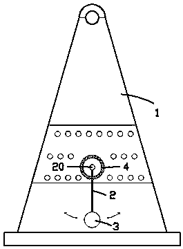
[0016] exist figure 1 In the first shown embodiment, the mechanical road induction isolation pier includes a conical pier body 1; a single pendulum assembly is arranged inside the conical pier body 1, and the single pendulum assembly includes a vertically downward pendulum 2. The lower end of the swing rod 2 is connected with a permanent magnet hammer head 3, which is a permanent magnetic ball, and the upper end of the swing rod 2 is connected with a swing rod shaft 20, and the swing rod shaft 20 drives a rotating bell 4. When the pendulum 2 is swung, the rotating bell 4 sounds.
[0017] During the use of the above-mentioned mechanical road induction isolation pier, if a vehicle approaches, the permanent magnetic hammer head 3 will be attracted by the vehicle to make the swing rod 2 swing outward, thereby driving the rotating bell 4 to rotate Make a sound to remind the driver to pay attention to driving or stop.
Embodiment 2
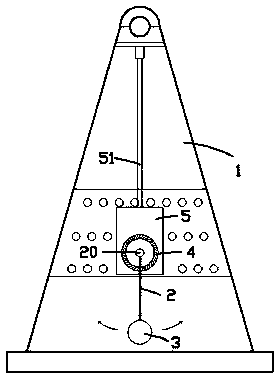
[0019] for figure 2 The second embodiment shown is different from the first embodiment in that the swing rod shaft 20 is horizontally connected to a vertical base plate 5, and the vertical base plate 5 is fixed on a base plate from the tapered pier body 1. The top of the inner chamber extends downwards and can only rotate around its own axis on the turning vertical rod 51; thus, when the vehicle approaches the conical pier 1 from different directions, by means of the rotating vertical rod 51, the vertical The rotation of the straight base plate 5 enables the swing link 2 to always swing towards the vehicle, so as to improve the sensitivity of the swing link to the vehicle.
Embodiment 3
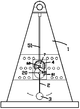
[0021] for image 3 , Figure 4 The third embodiment shown is different from the second embodiment in that a large gear 61 that rotates synchronously with the swing rod 2 is fixed on the swing rod shaft 20, and the large gear 61 meshes with a small gear 62; the small gear 62 drives the rotating bell 4 to rotate and sound; and the flywheel 7 is fixed on the connecting shaft between the pinion 62 and the rotating bell 4; and, only a section of the inferior arc on the large gear 61 is formed with gear teeth 611; image 3 As shown, when the swing rod 2 is in the vertically downward state, the section of gear teeth 611 is directly above the large gear 61; when the swing rod 2 swings to the maximum swing angle, as shown in FIG. Figure 4 As shown, the gear teeth 611 on this segment of the inferior arc are turned away from the pinion 62, so that the large gear 61 and the pinion 62 are in a non-meshing state; thus, when the swing bar 2 is attracted by the vehicle and outward When sw...
PUM
 Abstract
Description
Claims
Application Information
 - R&D
- Intellectual Property
- Life Sciences
- Materials
- Tech Scout
- Unparalleled Data Quality
- Higher Quality Content
- 60% Fewer Hallucinations
Browse by: Latest US Patents, China's latest patents, Technical Efficacy Thesaurus, Application Domain, Technology Topic, Popular Technical Reports.
© 2025 PatSnap. All rights reserved.Legal|Privacy policy|Modern Slavery Act Transparency Statement|Sitemap|About US| Contact US: help@patsnap.com


