
Angle-adjustable welding head structure of welding machine

A welding machine and welding head technology, which is applied in the direction of welding rod characteristics, supporting electrode clamp device, electrode supporting device, etc., can solve the problems of reducing welding work efficiency, inconvenient use, and non-adjustable welding head height, etc., so as to increase practicability, The effect of increasing the welding distance

Inactive Publication Date: 2018-02-09
黄石市盛兴机械科技股份有限公司
View PDF0 Cites 11 Cited by
  • Summary
  • Abstract
  • Description
  • Claims
  • Application Information

AI Technical Summary

Problems solved by technology

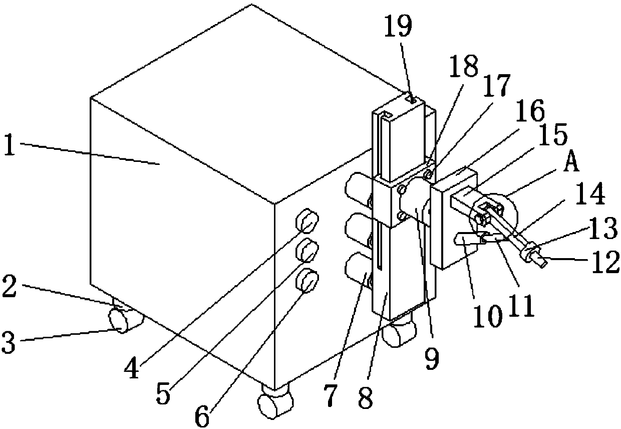
[0002] A welding machine is an electrical appliance that provides a certain power supply for welding. Commonly used welding machines are divided into three types: DC, AC, and pulse from the welding current, but AC and DC inverter welding machines are commonly used. The main components of the welding machine are A step-down transformer, the two ends of the secondary coil are the workpiece to be welded and the welding rod. When working, the arc is ignited, and the welding rod is fused to the gap of the workpiece in the high temperature of the arc. The existing welding head structure, when in use The angle of the welding head cannot be adjusted, and the operator needs to rotate the plate during welding, which brings unnecessary troubles and reduces the working efficiency of welding. In addition, the height of the welding head cannot be adjusted, which is inconvenient to use

Method used


Image

  • Angle-adjustable welding head structure of welding machine
  • Angle-adjustable welding head structure of welding machine
  • Angle-adjustable welding head structure of welding machine

Examples


Embodiment Construction

[0014] The following will clearly and completely describe the technical solutions in the embodiments of the present invention with reference to the accompanying drawings in the embodiments of the present invention. Obviously, the described embodiments are only some, not all, embodiments of the present invention. Based on the embodiments of the present invention, all other embodiments obtained by persons of ordinary skill in the art without making creative efforts belong to the protection scope of the present invention.

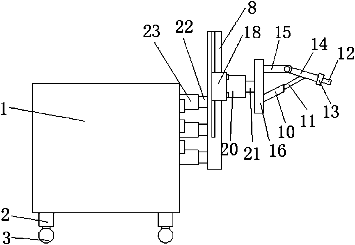
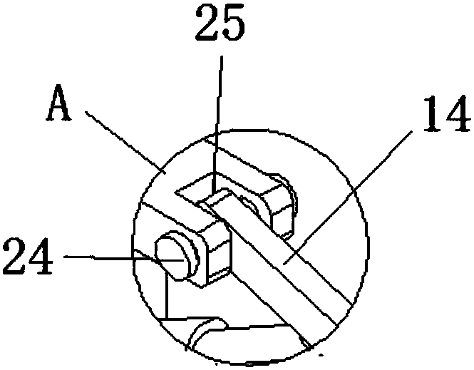
[0015] see Figure 1-3 , the present invention provides a technical solution: a welding head structure with adjustable angle, including a welding machine body 1, the four corners of the lower surface of the welding machine body 1 are provided with supporting legs 2, and the bottom ends of the supporting legs 2 are provided with Roller 3, convenient mobile device, the right side of welder body 1 is provided with first control switch 4, motor switch 5 and second...


PUM


Abstract

The invention discloses an angle-adjustable welding head structure of a welding machine, which comprises a welding machine body, and a first control switch, a motor switch and a second control switch are arranged on the right side of the welding machine body. There is a telescopic device in the middle of the surface, and one end of the telescopic device is provided with a strip plate. The side surface of the strip plate is slidingly mounted with a slide plate. The slide plate is fastened to the strip plate by screws. One end of the connecting plate is provided with a connecting plate, the upper part of the side surface of the connecting plate is provided with a supporting plate, the end of the supporting plate is provided with a through groove, and a connecting rod is arranged in the through groove, and the connecting rod is rotationally connected with the supporting plate through a rotating rod. One end is provided with a welding head installation seat, and the side surface of the welding head installation seat is provided with a welding head. The welding head structure of the welding machine with adjustable angle is convenient to move, the height of the welding head can be adjusted, and the angle of the welding head can be adjusted, and the angles are various, which brings great convenience to the use.

Description

technical field [0001] The invention relates to the technical field of welding machine equipment, in particular to an angle-adjustable welding head structure of a welding machine. Background technique [0002] A welding machine is an electrical appliance that provides a power supply with certain characteristics for welding. Commonly used welding machines are divided into three types: DC, AC, and pulse from the welding current, but AC and DC inverter welding machines are commonly used. The main components of the welding machine are A step-down transformer, the two ends of the secondary coil are the workpiece to be welded and the welding rod. When working, the arc is ignited, and the welding rod is fused to the gap of the workpiece in the high temperature of the arc. The existing welding head structure, when in use The angle of the welding head is not adjustable, and the operator needs to rotate the plate during welding, which brings unnecessary troubles and reduces the workin...

Claims


Application Information

Patent Timeline
IPC IPC(8): B23K9/28
CPCB23K9/287
Inventor 郭熙斌
Owner 黄石市盛兴机械科技股份有限公司
Learn More