A vehicle-mounted non-contact catenary geometric parameter dynamic detection system and method
What is AI technical title?
AI technical title is built by Patsnap AI team. It summarizes the technical point description of the patent document.
A geometric parameter, dynamic detection technology, applied in the field of detection, can solve the problems of complex structure, low precision, difficult installation, etc., to achieve the effect of high detection precision, wide versatility and easy installation
Active Publication Date: 2021-06-04
ZHUZHOU JIACHENG TECH DEV CO LTD
View PDF8 Cites 0 Cited by
Summary
Abstract
Description
Claims
Application Information
AI Technical Summary
This helps you quickly interpret patents by identifying the three key elements:
Problems solved by technology
Method used
Benefits of technology
Problems solved by technology
[0004] (1) Using contact detection, it is difficult to install, complex in structure and low in precision;
[0005] (2) Using a non-contact single sensor, the detection effect is poor and the accuracy is low;
[0006] (3) There is no vehicle body vibration compensation, or the vehicle body vibration compensation is not in place, and the test result deviates greatly from the actual measurement value
[0007] The above schemes cannot achieve the purpose of guiding the state maintenance of electrified railways, and cannot meet the requirements for the operation of electrified railways
Method used
Image
Click on the blue label to locate the original text in one second.
Reading with bidirectional positioning of images and text.
Examples
Embodiment 1
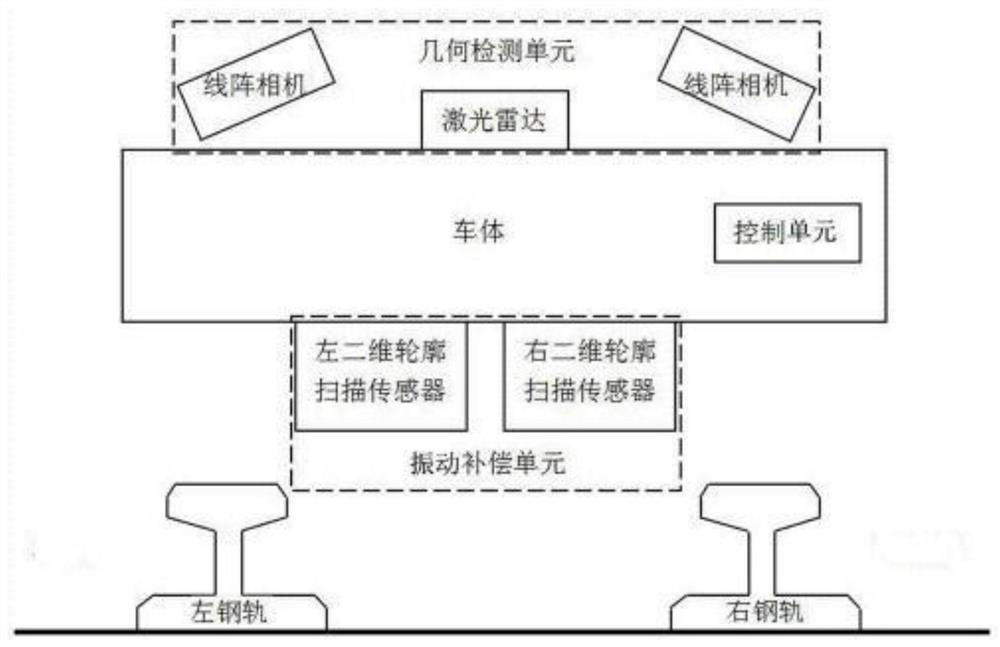
[0035] This embodiment provides a vehicle-mounted non-contact catenary dynamic detection system for geometric parameters. Such as figure 1 As shown, it includes a geometric detection unit located on the top of the vehicle body for detecting the catenary, a control unit installed inside the vehicle body, and a vibration compensation unit located at the bottom of the vehicle body for detecting the vibration of the vehicle body.
[0036] The vibration compensation unit is located at the bottom of the vehicle and is composed of two two-dimensional contour scanning sensors; and the geometric detection unit and the vibration compensation unit are installed in the same cross section of the vehicle body perpendicular to the rail.
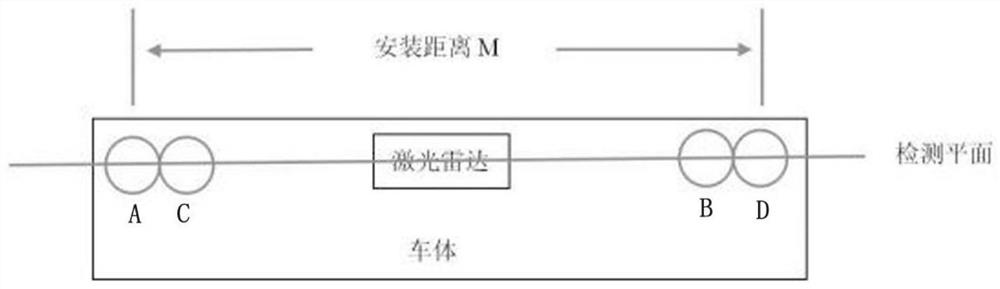
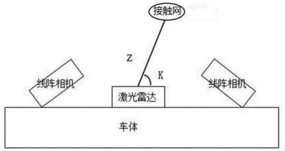
[0037] Such as figure 2 , image 3 As shown, the geometric detection unit is located in the center of the car body, including a lidar, four line array cameras, light sources and mounting brackets. The lidar and line array cameras are installed on the top...
Embodiment 2
[0042] This embodiment provides a detection method using Embodiment 1.
[0043] Include the following steps:
[0044] S1. Use the lidar and the line array camera to detect the spatial position of the catenary on the roof.
[0045] Before the actual detection, the line scan camera is calibrated, the process is as follows.
[0046] S11. Using the regression technique, perform camera calibration on the line scan camera used for measuring the catenary in advance.
[0047] S111 acquires the training data, and obtains the corresponding relationship between the world coordinates and the pixel coordinates of the line array camera;
[0048]During the calibration process, objects with known spatial position information are usually used as scenes for shooting, and such objects are called calibration objects. In this embodiment, a black strip is used as a calibration object, which is photographed from several perspectives. Considering that the target surface of the line scan camera is...
PUM
Abstract
The invention relates to the field of measurement technology, and discloses a vehicle-mounted non-contact catenary geometric parameter dynamic detection system and method. The detection system includes a geometric detection unit arranged on the roof for detecting catenary, a control unit arranged in the vehicle body, and a vibration compensation unit arranged at the bottom of the vehicle for detecting the vibration of the vehicle body; the geometric detection unit includes laser radar, A line array camera and a light source; the lidar is arranged in the center of the geometric detection unit; the line array cameras are provided with two groups, two for each group, and two groups of line array cameras are respectively arranged on both sides of the lidar, and the line array cameras of the same group The array camera is arranged obliquely relative to the roof; the laser radar and the line array camera are distributed on the same straight line, and the scanning area of the laser radar and the detection area of the line array camera are on the same detection plane; the light sources are arranged on both sides of the laser radar. The detection system and method have high detection precision, simple structure and convenient installation.
Description
technical field [0001] The invention relates to the technical field of detection, and more specifically, to a system and method for dynamic detection of geometric parameters of a vehicle-mounted non-contact catenary. Background technique [0002] The catenary is a high-voltage transmission line erected in a "zigzag" shape along the sky above the rails in the electrified railway for pantographs to take current. The good contact between the catenary wire and the pantograph is the key to ensure the quality of electric locomotive current intake. With the rapid development of China's railway industry and the continuous increase of electrified railway mileage, the intensity and difficulty of catenary maintenance are constantly increasing. In order to improve the fault detection speed and ensure the safe operation of the line, it is particularly urgent to develop a high-speed and high-precision catenary detection equipment. In July 2012, the China Railway Corporation released the...
Claims
Application Information
Patent Timeline
Application Date:The date an application was filed.
Publication Date:The date a patent or application was officially published.
First Publication Date:The earliest publication date of a patent with the same application number.
Issue Date:Publication date of the patent grant document.
PCT Entry Date:The Entry date of PCT National Phase.
Estimated Expiry Date:The statutory expiry date of a patent right according to the Patent Law, and it is the longest term of protection that the patent right can achieve without the termination of the patent right due to other reasons(Term extension factor has been taken into account ).
Invalid Date:Actual expiry date is based on effective date or publication date of legal transaction data of invalid patent.

