Hydraulic time difference braking device

A hydraulic braking technology, applied to bicycle accessories, bicycle brakes, etc., can solve the problems of starting braking, crash accidents, errors, etc., and achieve the effect of increasing braking force, improving braking efficiency and safety

Active Publication Date: 2019-12-06
张瑞龙
View PDF8 Cites 0 Cited by
  • Summary
  • Abstract
  • Description
  • Claims
  • Application Information

AI Technical Summary

Problems solved by technology

[0002] At present, in the braking system of various vehicles, such as automobiles, the brakes of the front and rear wheels use a master cylinder to simultaneously drive the oil pressure output pipes corresponding to the brakes of the front and rear wheels to generate braking force. As a result of the driver’s braking action, although the master cylinder drives the brake oil pressure output pipes of the front and rear wheels at the same time to generate braking force, but because the distance between the rear wheels and the master cylinder is farther than that of the front wheels, the front wheels brake. When the brake has started, the rear wheel brakes start to brake and wait for half a beat. Because most of the vehicles adopt the rear wheel drive structure, the front wheel starts to brake, and the rear wheel continues to output large kinetic energy. , a risk factor that is likely to cause vehicle drift
[0003] For two-wheel locomotives and bicycles, since the brake drive components of the front and rear wheels are respectively distributed on the left and right sides of the handle, the braking action of the front or rear wheels depends on the result of the rider's own operation. Irreversible results will be caused by the rider's operation error. For example, due to the common brake operation error, the front wheel brake is activated first, resulting in the continuous output of rear wheel power, resulting in a major crash accident.

Method used


Image

  • Hydraulic time difference braking device
  • Hydraulic time difference braking device
  • Hydraulic time difference braking device

Examples


Embodiment Construction

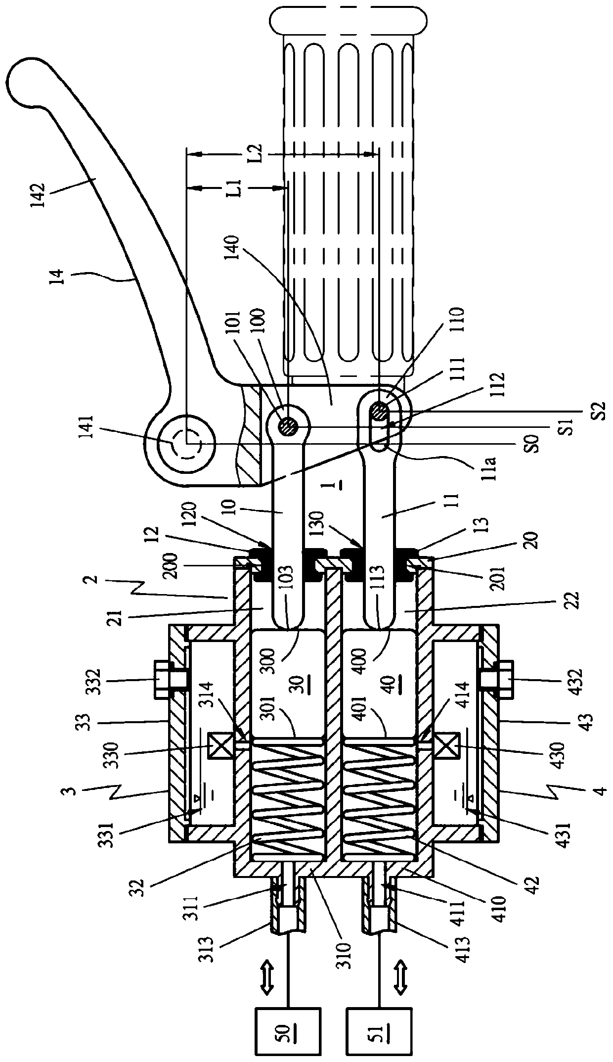
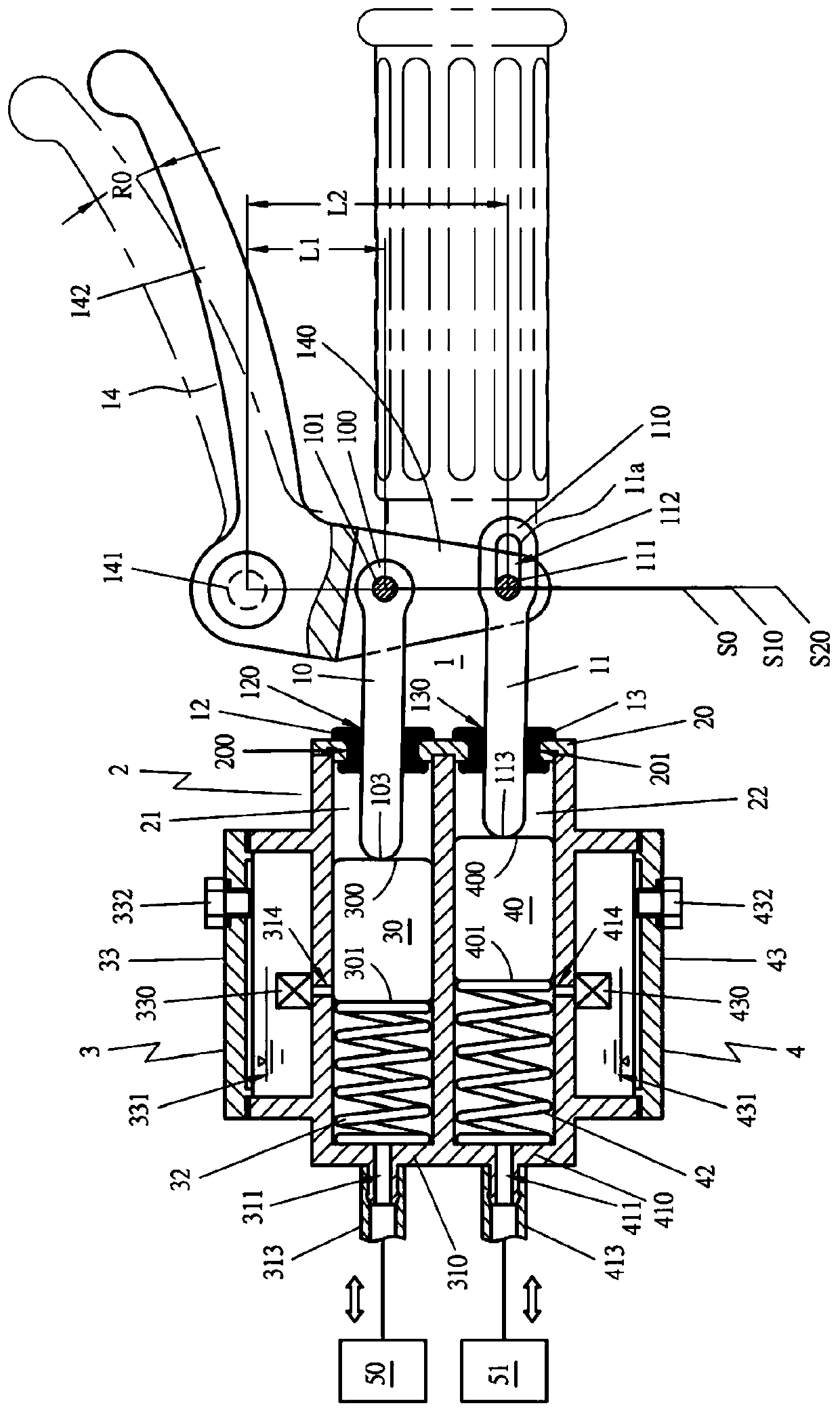
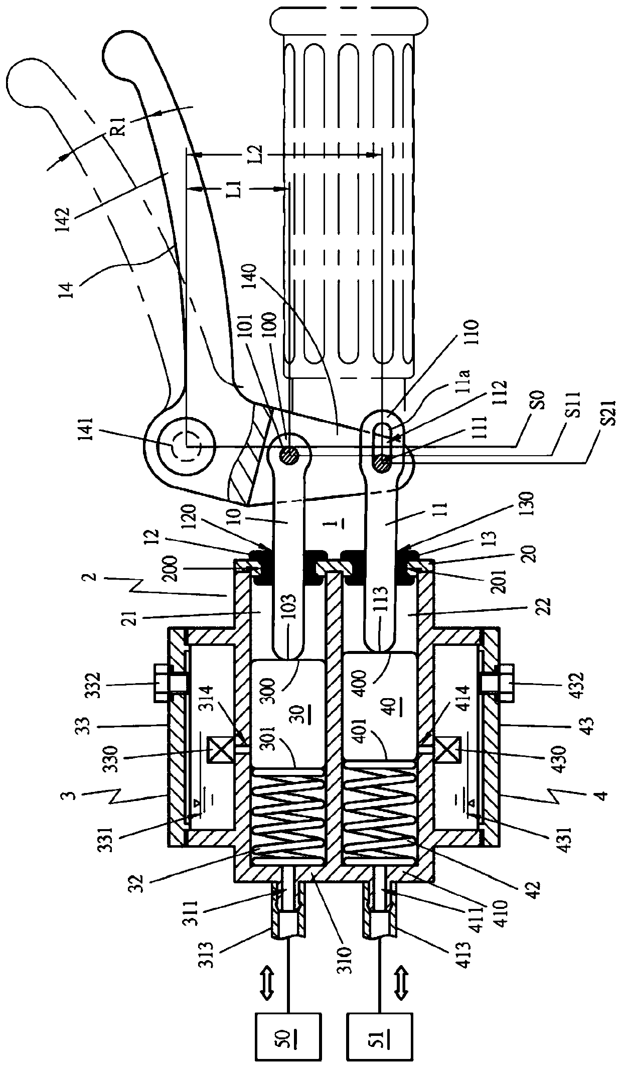
[0062] In order to allow the public to further understand the hydraulic time difference braking device described in the present invention, the best implementation mode is explained as follows with reference to the accompanying drawings:

[0063] like Figure 1-4 As shown, the hydraulic time difference braking device of the present invention at least includes: a driving mechanism 1, a first driving rod 10, a second driving rod 11 and a brake driving element 14, the outer end 100 of the first driving rod 10 The supporting shaft 101 passes through, and is combined with the driving part 140 of the brake drive element 14 through the supporting shaft 101. The aforementioned first driving rod 10 and the supporting shaft 101 are movable structures. In this state, the first driving rod 10 is driven by the brake driving element 14 to freely displace along a certain track. The first driving rod 10 passes through the middle hole 120 of the first rod seat 12 with appropriate flexibility, ...


PUM


Abstract

The invention relates to an oil pressure type time difference braking device. The device comprises a driving mechanism, the driving mechanism is provided with a first driving rod and a second drivingrod, and the first driving rod and the second driving rod partly extend into a first cavity and a second cavity of a shell; the first driving rod and the second driving rod are connected with a braking driving element, the braking driving element drives the first driving rod in real time and makes a first piston of a first pump mechanism generate displacement, so that the first braking force is output to a back wheel brake, and in the time difference that the first piston reaches to the set displacement distance, the first piston can be added, drives a second driving rod at the same time, andpushes a second piston of a second pump mechanism generate displacement, so that the second braking force is output to a front wheel brake. In this way, the first braking force and the second brakingforce with time difference are generated only by one braking motion, then the second braking force which is generated by the second pump mechanism is larger than the first braking force which is generated by the first pump mechanism, so that the braking force of the front wheel brake is increased, and the braking efficiency and safety of a vehicle are more improved.

Description

technical field [0001] The present invention relates to a hydraulic time-difference braking device, especially a braking action by a rider or a driver, within the time difference when the first piston of the first pump mechanism reaches the set displacement distance, it will join and simultaneously Push the second piston of the second pump mechanism to generate displacement, and output the second braking force to the front wheel brake. In this way, it is possible to use the first pump mechanism and the second pump mechanism with one braking action of the rider or driver. At the beginning, the first braking force and the second braking force with a time difference are generated, so that the rear wheel brake and the front wheel brake produce a braking action with a time difference, and then the second braking force generated by the second pump mechanism The power is greater than the first braking force generated by the first pump mechanism, so as to increase the braking force of...

Claims


Application Information

Patent Timeline
Patent Type & Authority Patents(China)
IPC IPC(8): B62L3/02B62L3/08
CPCB62L3/023B62L3/08
Inventor 张瑞龙
Owner 张瑞龙
Why Eureka
Try Eureka