Pump shaft sealing structure with wearing clearance compensation function

A technology of sealing structure and wear clearance, which is applied to the components, pumps, and pump components of the pumping device for elastic fluids, which can solve the problem of uneven butt joint contact surfaces of friction pairs, increase the gap between dynamic and static rings, and reduce mechanical seals. Service life and other issues, to achieve the effect of good sealing effect, simple adjustment and prolong service life

Inactive Publication Date: 2018-02-16
XIANGYANG WU ER WU PUMP IND
View PDF4 Cites 1 Cited by
  • Summary
  • Abstract
  • Description
  • Claims
  • Application Information

AI Technical Summary

Problems solved by technology

[0003] The purpose of the present invention is to solve the problem of using springs as wear gap compensation in traditional pump seals. The springs are prone to failure, and the contact surfaces between the friction pairs caused by the point contact of the springs are uneven butt joints, so that the gap between the dynamic and static rings increases and becomes invalid, reducing the To solve the problems such as the service life of the mechanical seal, and provide a pump shaft seal structure with wear gap compensation

Method used


Image

  • Pump shaft sealing structure with wearing clearance compensation function
  • Pump shaft sealing structure with wearing clearance compensation function

Examples


Embodiment

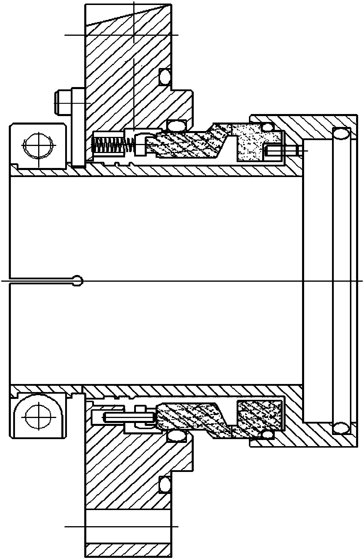
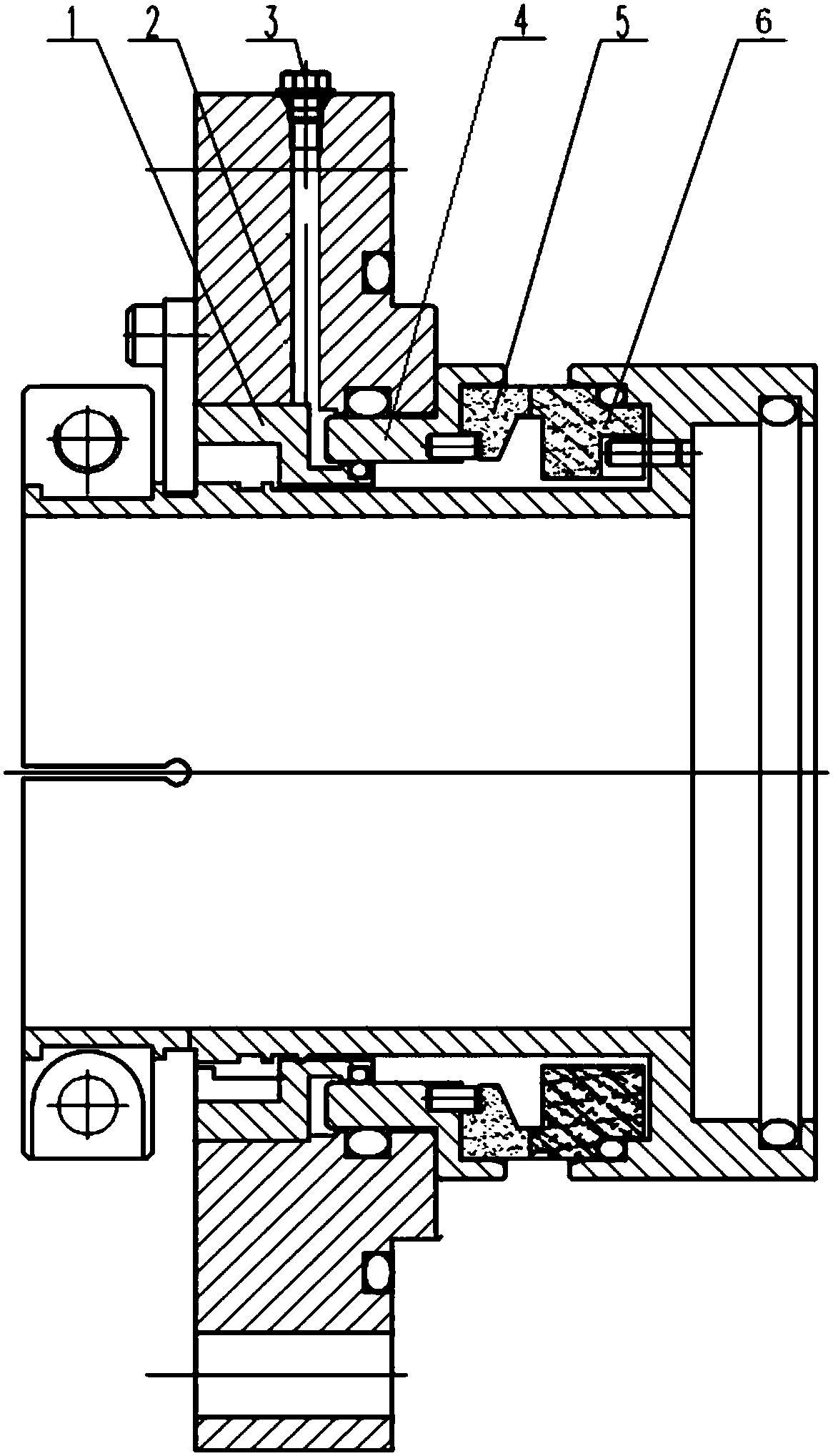
[0019] A pump shaft seal structure with wear clearance compensation of the present invention, such as figure 2 As shown, it includes pump cover body 2, tightening plug 3, front connecting ring 4, rear connecting ring 1, static ring friction pair 5, and moving ring friction pair 6;

[0020] The front end of the front connecting ring 4 is processed with a friction pair mounting seat, and the outer wall of the rear end of the front connecting ring 4 is processed with a stepped positioning platform;

[0021] The outer wall of the rear connecting ring 1 is a stepped cylindrical surface;

[0022] The dynamic ring friction pair 6 is fixed to the pump shaft sleeve, the static ring friction pair 5 is fixed in the friction pair mounting seat at the front end of the front connecting ring 4, the rear end of the front connecting ring 4 is inserted into the front end of the inner cavity of the pump cover body 2, and passes through the The stepped positioning platform on the outer wall of ...


PUM


Abstract

The invention relates to a pump shaft sealing structure with a wearing clearance compensation function and belongs to the field of modern fluid machines. The pump shaft sealing structure comprises a pump cover body, a screwing plug, a front connecting ring, a rear connecting ring, a static ring friction pair and a dynamic ring friction pair. The screwing plug is screwed into a liquid injection hole and then pressurizes hydraulic media that a liquid storage cavity is filled with so that the static ring friction pair can tightly forwards push the dynamic ring friction pair; and after a clearancebetween the contact surfaces of the static ring friction pair and the dynamic ring friction pair becomes large due to wearing, the screwing plug is screwed downwards continuously, the hydraulic mediathat the liquid storage cavity is filled with are pressurized again, and the friction clearance between the static ring friction pair and the dynamic ring friction pair is compensated. According to the pump shaft sealing structure, the sealing effect is good, wearing compensation adjusting is easy, during friction clearance compensation, surface contact is achieved between the hydraulic media andthe rear end of the static ring friction pair, the axially forward moving direction of the static ring friction pair is ensured, the reliability of mechanical sealing is improved, and the service life of a mechanical seal is prolonged.

Description

technical field [0001] The invention relates to a pump shaft sealing structure with wear clearance compensation, which belongs to the field of modern fluid machinery. Background technique [0002] The seal is an indispensable part of the pump, and it is the guarantee for the normal, stable and safe operation of the pump. The sealing system ensures that the medium will not leak, protects the site environment, and at the same time avoids the harm to people caused by the leakage of toxic and harmful media. Traditional pump shaft seal structure such as figure 1 As shown, it includes a spring, a static ring assembly and a moving ring assembly. The static ring assembly is installed in the inner cavity of the pump cover body, and the static ring assembly remains stationary with the pump cover body; The shaft rotates and rotates, and the friction pairs of the static ring assembly and the moving ring assembly are closely matched, and the sealing effect is guaranteed by the nano-sca...

Claims


Application Information

Patent Timeline
Patent Type & Authority Applications(China)
IPC IPC(8): F04D29/10F04D29/12
CPCF04D29/10F04D29/12
Inventor 李家虎杨松徐衡丁康
Owner XIANGYANG WU ER WU PUMP IND
Why Eureka
Try Eureka