
Computer forming knife

A forming knife and computer technology, applied in the field of forming knives, can solve the problems of low safety performance, waste of cost, and blade exposure to the outside, and achieve the effects of saving replacement costs, improving safety performance, and convenient grinding

Inactive Publication Date: 2018-02-23
江苏西夏墅工具产业研究院有限公司
View PDF0 Cites 0 Cited by
  • Summary
  • Abstract
  • Description
  • Claims
  • Application Information

AI Technical Summary

Problems solved by technology

[0002] As everyone knows, the computer forming knife is a kind of auxiliary device used in the production process of the computer casing, which is processed, and it is widely used in the field of production and processing; the existing computer forming knife includes a knife handle and a blade, and the blade is arranged on The left end of the knife handle; when using this kind of computer forming knife, you only need to install it on the processing device, and then process the computer shell; when using this kind of computer forming knife, it is found that the length of the knife handle is too long, which leads to finger force when grinding. The distance between the force point and the edge of the blade is long, which makes it inconvenient to finely grind the blade; and the blade is exposed to the outside, and the operator is easily scratched by the blade when handling it, and the safety performance is low; and the consumption speed of the blade It is faster than the consumption rate of the handle, and the handle and the blade need to be replaced at the same time when replacing, which is wasteful and costly

Method used


Image

  • Computer forming knife
  • Computer forming knife

Examples


Embodiment Construction

[0013] The specific embodiments of the present invention will be described in further detail below with reference to the accompanying drawings and embodiments. The following examples are intended to illustrate the present invention, but not to limit the scope of the present invention.

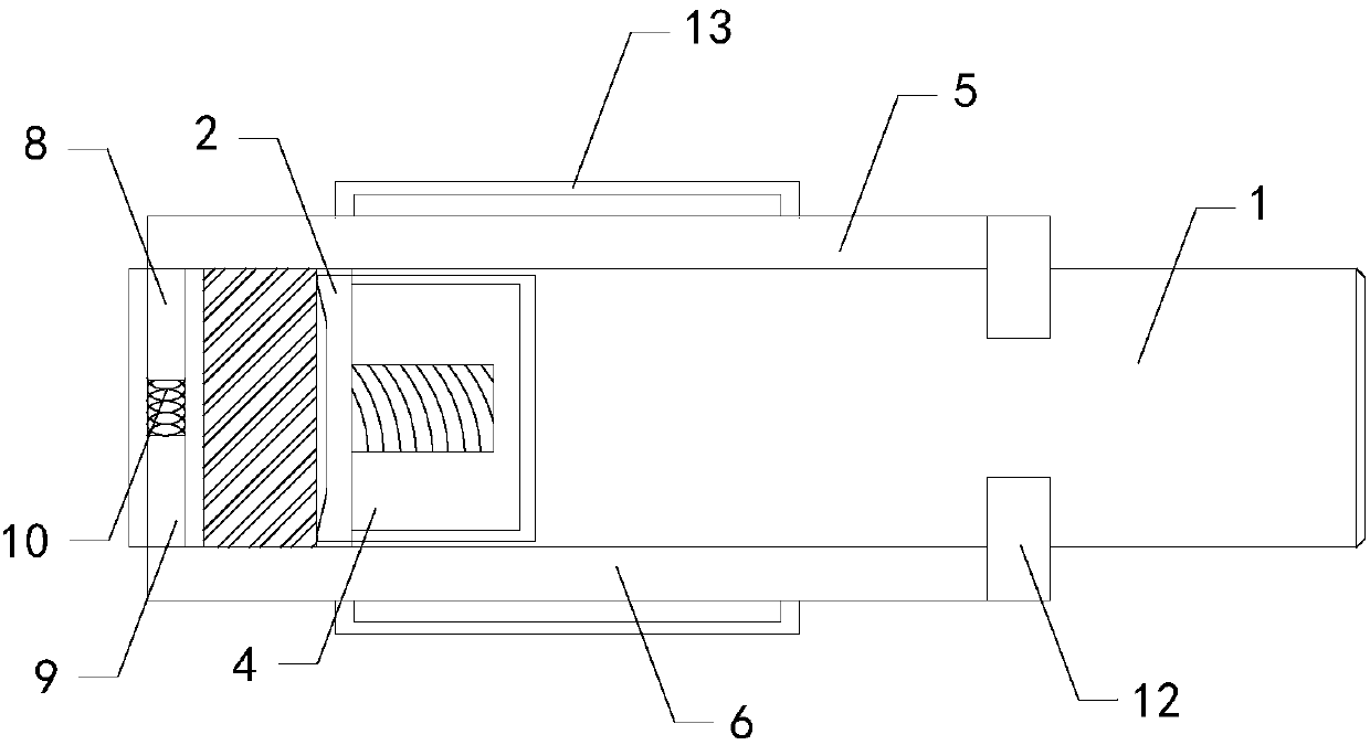
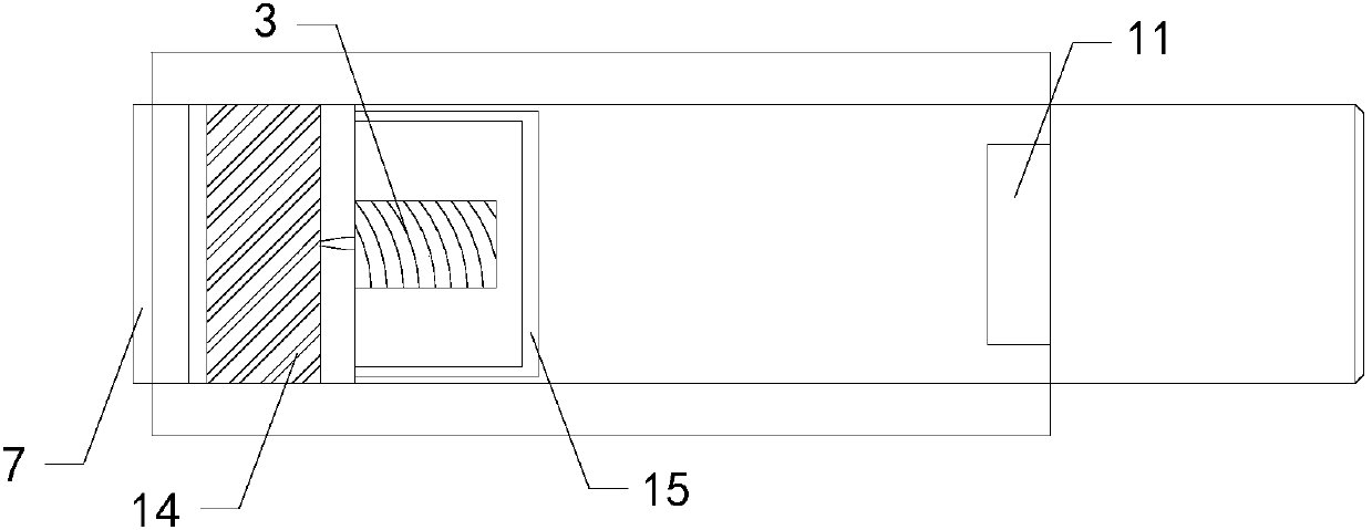
[0014] like Figure 1 to Figure 2 As shown, a computer shaped knife of the present invention includes a handle 1 and a blade 2; also includes a connecting rod 3, the connecting rod is arranged at the right end of the blade, and an external thread structure is provided on the outer side wall of the connecting rod; it also includes a connecting block 4. The left end of the connecting block is provided with a fixing groove that matches the connecting rod, and the inner side wall of the fixing groove is provided with an internal thread structure that matches the external thread structure of the connecting rod. The connecting rod is screwed into the fixing groove, and the left end of the handle A p...


PUM


Abstract

The present invention relates to the technical field of forming knives, in particular to a computerized forming knife, which can shorten the distance between the force point of the finger and the edge of the blade during grinding, so as to facilitate fine grinding of the blade; at the same time, the blade can be shielded to improve safety performance ; and only the blade can be replaced to save replacement cost; it includes a handle and a blade; it also includes a connecting rod, which is arranged at the right end of the blade, and an external thread structure is arranged on the outer wall of the connecting rod; it also includes a connecting block, connecting The left end of the block is provided with a fixing groove matching the connecting rod, and the inner wall of the fixing groove is provided with an internal thread structure matching the external thread structure of the connecting rod. The connecting rod is screwed in the fixing groove, and the left end of the handle is provided with a slot, the connecting block is inserted into the placement slot; a blocking device is also included, and the blocking device is arranged outside the knife handle.

Description

technical field [0001] The invention relates to the technical field of forming tools, in particular to a computer forming tool. Background technique [0002] As we all know, a computer-shaped knife is an auxiliary device used for processing computer shells in the production process, and it is widely used in the field of production and processing; the existing computer-shaped knife includes a handle and a blade, and the blade is set at The left end of the handle; when using this computer-shaped knife, it only needs to be installed on the processing device, and then the computer shell can be processed; the length of the handle of this computer-shaped knife is found to be long during use, which causes the fingers to be applied during grinding. The distance between the force point and the blade edge of the blade is long, which makes it inconvenient to grind the blade carefully; and the blade is exposed to the outside, and the operator is easily scratched by the blade when taki...

Claims


Application Information

Patent Timeline
IPC IPC(8): B23D79/00
CPCB23D79/00
Inventor 马嘉豪
Owner 江苏西夏墅工具产业研究院有限公司
Learn More