Compensation module, grid drive unit, circuit, driving method thereof and display device

A gate drive and compensation module technology, which is applied in the field of gate drive units, circuits and its drive methods, display devices, and compensation modules, and can solve problems such as failure to output gate drive signals and affecting normal display.

Inactive Publication Date: 2018-02-27
BOE TECH GRP CO LTD +1
View PDF3 Cites 10 Cited by
  • Summary
  • Abstract
  • Description
  • Claims
  • Application Information

AI Technical Summary

Problems solved by technology

[0004] The main purpose of the present invention is to provide a compensation module, a gate drive unit, a circuit and its driving method, and a display device to solve the problem of the potential of the pull-up node in the existing gate drive unit due to the existence of the touch phase or due to low frequency When the output is lowered, the corresponding gate drive signal cannot be output, which affects the normal display problem

Method used


Image

  • Compensation module, grid drive unit, circuit, driving method thereof and display device
  • Compensation module, grid drive unit, circuit, driving method thereof and display device
  • Compensation module, grid drive unit, circuit, driving method thereof and display device

Examples


no. 1 Embodiment

[0106] The first specific embodiment of the gate drive circuit of the present invention includes a multi-level gate drive unit;

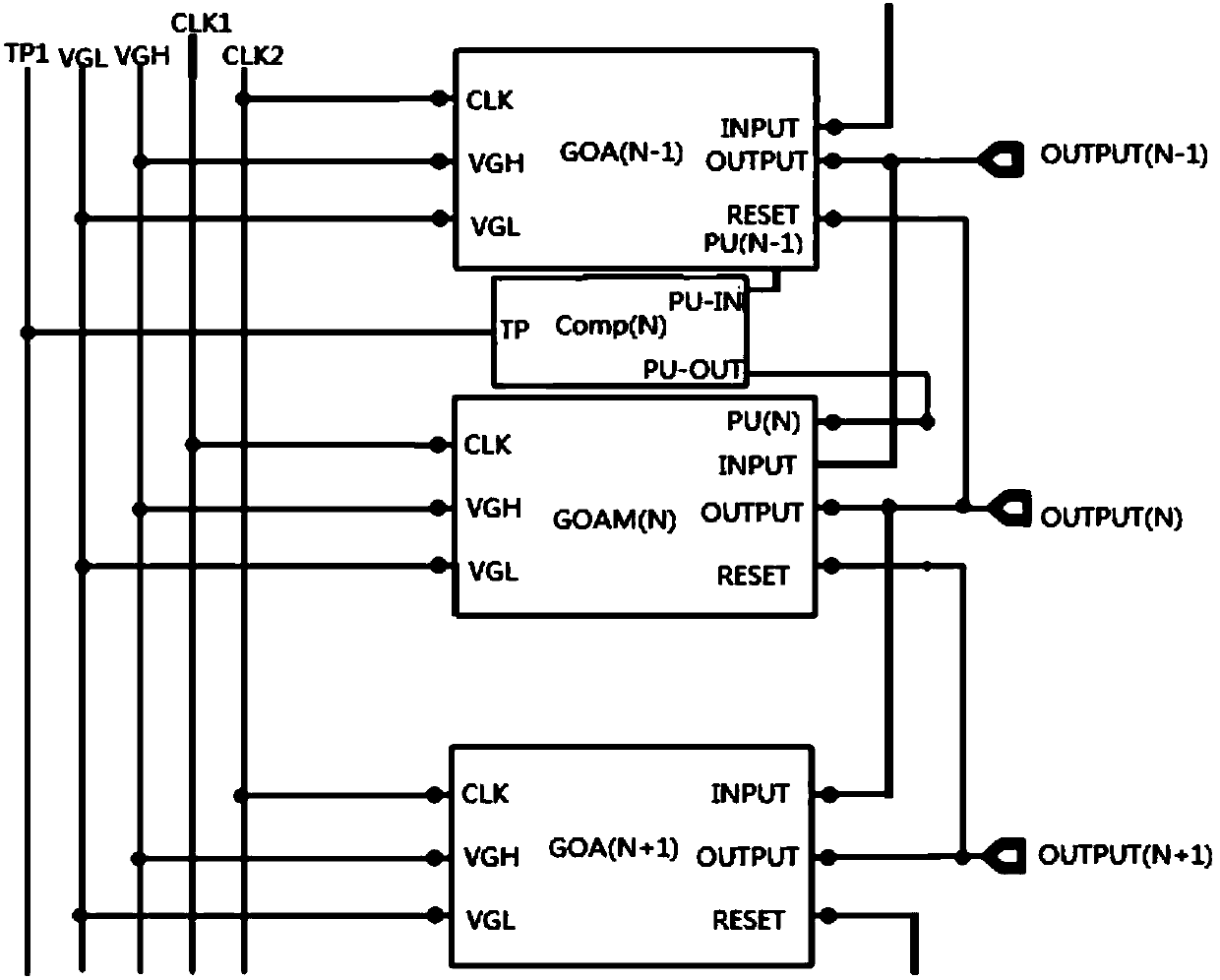
[0107] exist image 3 , only the three-level gate drive unit included in the first specific embodiment of the gate drive circuit according to the present invention is drawn: the N-1th level gate drive unit GOA(N-1), the Nth level gate The pole drive unit and the N+1th level gate drive unit GOA(N+1); N is an integer greater than 1;

[0108] Both GOA(N-1) and GOA(N+1) are existing gate drive units;

[0109] The gate driving unit of the Nth stage is the gate driving unit described in the embodiment of the present invention;

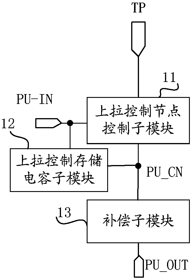
[0110] The Nth-level gate drive unit includes an Nth-level shift register module GOAM(N) and an N-level compensation module Comp(N);

[0111] In GOA(N-1), GOA(N+1) and GOAM(N), the one labeled OUTPUT is the gate drive signal output terminal, the one labeled RESET is the shift reset terminal, and the one labeled CLK is the shift...


PUM


Abstract

The invention provides a compensation module, a grid drive unit, a circuit, a driving method thereof and a display device. The compensation module comprises a pull-up control node control submodule, apull-up control storage capacitance submodule and a compensation submodule, wherein under the control of a pull-up input end, a touch end signal input end is controlled to input a touch end signal toa pull-up control node; the first end of the pull-up control storage capacitance submodule is connected with the pull-up input end, and the second end of the pull-up control storage capacitance submodule is connected with the pull-up control node; under the control of the pull-up control node, the compensation submodule controls to conduct connection between the pull-up control node and the pull-up node voltage output end. The compensation submodule is additionally arranged to control the electric potential of the pull-up node voltage output end, and when the electric potential in the grid drive unit is reduced due to existence of the touch stage or low-frequency output, the electric potential of the pull-up node is controlled to rise through the pull-up node voltage output end.

Description

technical field [0001] The present invention relates to the technical field of display driving, in particular to a compensation module, a gate driving unit, a circuit and a driving method thereof, and a display device. Background technique [0002] GOA (Gate On Array, set The gate drive circuit on the array substrate) has the advantages of small footprint, low cost, and high integration, and is currently widely used by major panel manufacturers. In the prior art, when low frequency output is performed, the potential of the pull-up node of the gate driving unit also decreases. [0003] For GOA related to TDDI (Touch Display Driver Integrated, touch display driver integration), a touch phase is set between the two display phases. When touch scanning is performed in the touch phase, GOA needs to stop display driver scanning. In the future, GOA will perform display drive scanning, so as to realize the alternate operation of touch and display. Assuming that the GOA has a 2CLK ...

Claims


Application Information

Patent Timeline
Patent Type & Authority Applications(China)
IPC IPC(8): G09G3/36G09G3/3266
CPCG09G3/3266G09G3/3674G06F3/0412G06F3/04166G09G3/3677G09G2310/0286G11C19/28G09G2300/0819
Inventor 栗峰张亮马禹桑琦
Owner BOE TECH GRP CO LTD
Why Eureka
Try Eureka