
Action orchestration in fault domains

An entity and relationship technology, applied in the field of action choreography in the fault-tolerant domain, which can solve problems such as spending months, inefficient use, and unrealistic

Active Publication Date: 2018-02-27
MICROSOFT TECH LICENSING LLC
View PDF7 Cites 0 Cited by
  • Summary
  • Abstract
  • Description
  • Claims
  • Application Information

AI Technical Summary

Problems solved by technology

However, at this rate, any maintenance covering all of the racks in the 3,500-rack infrastructure could take months to complete
This approach is extremely inefficient and even impractical for some large systems

Method used


Image

  • Action orchestration in fault domains
  • Action orchestration in fault domains
  • Action orchestration in fault domains

Examples


Embodiment Construction

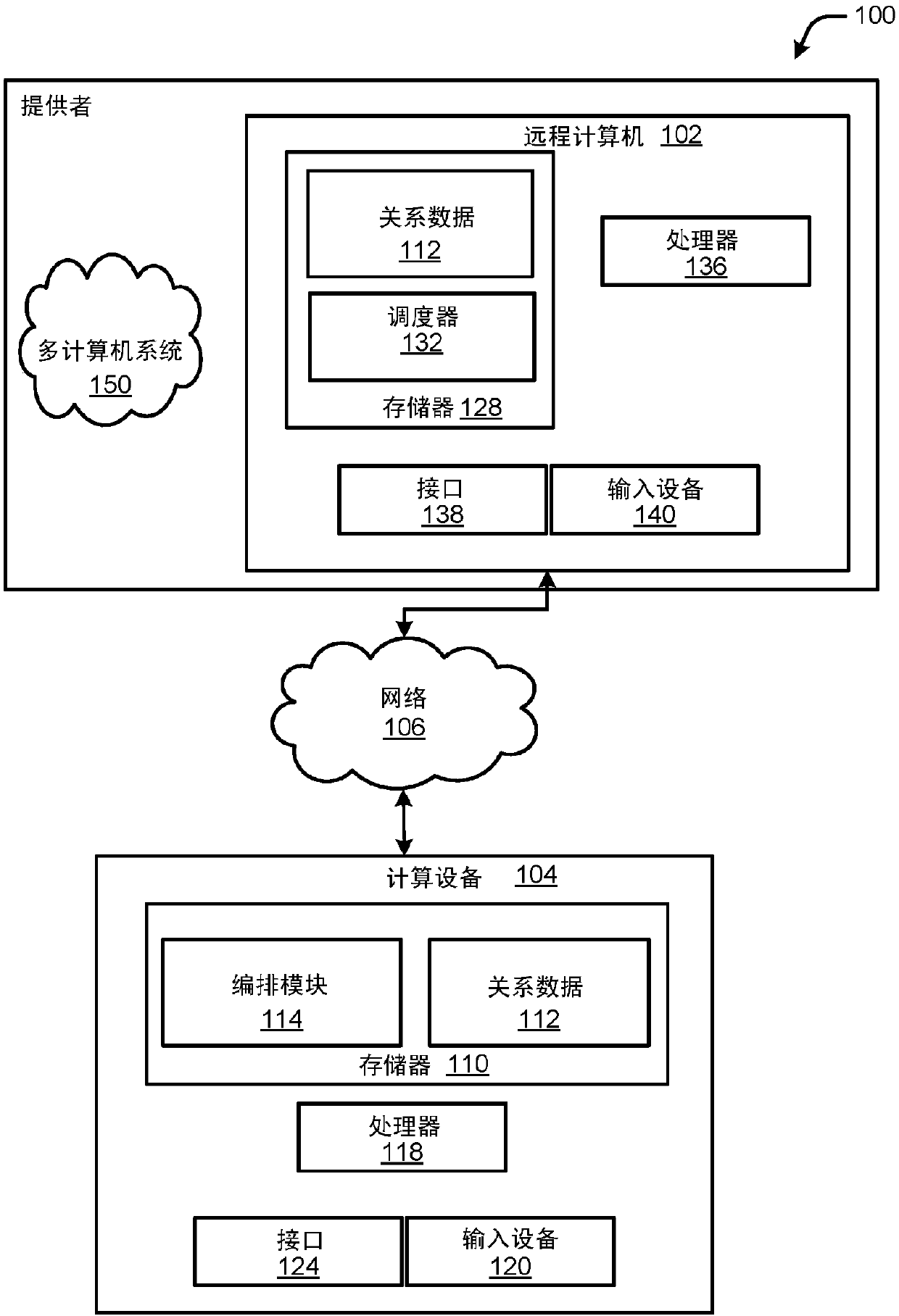
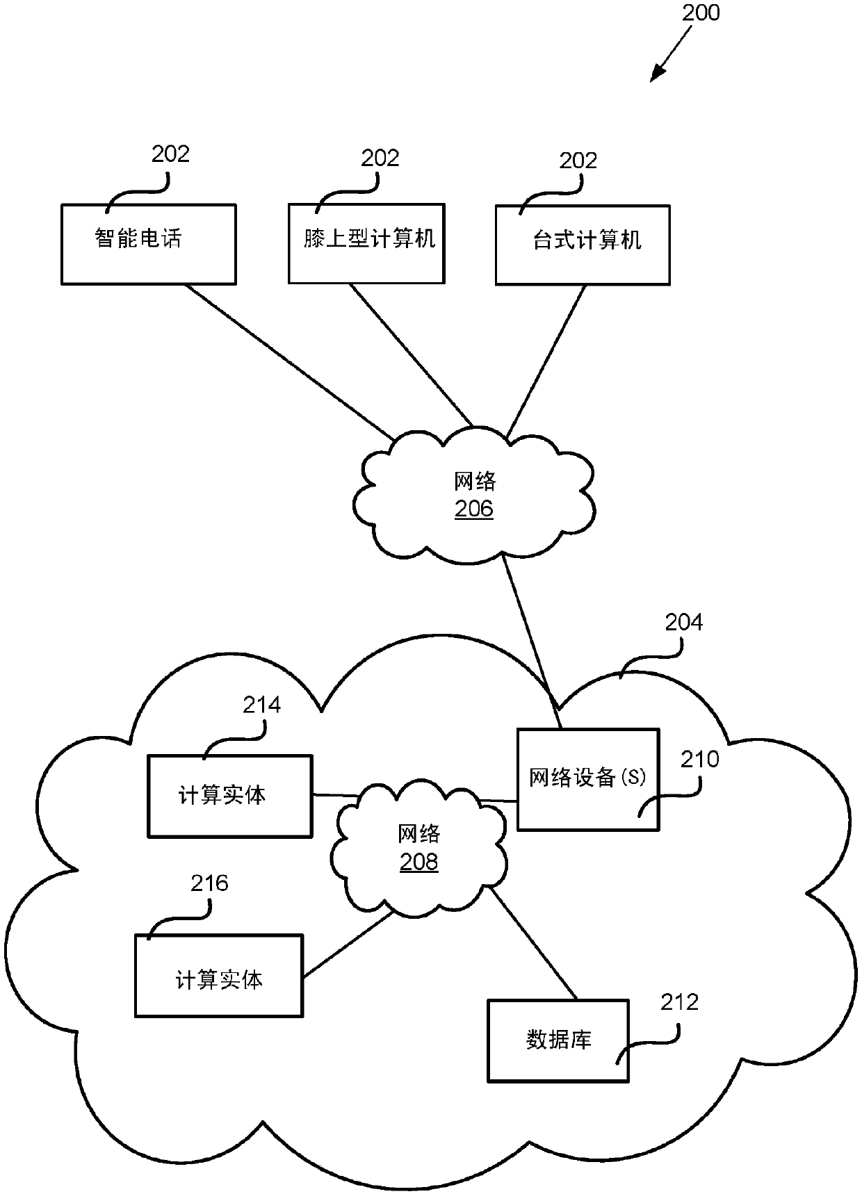
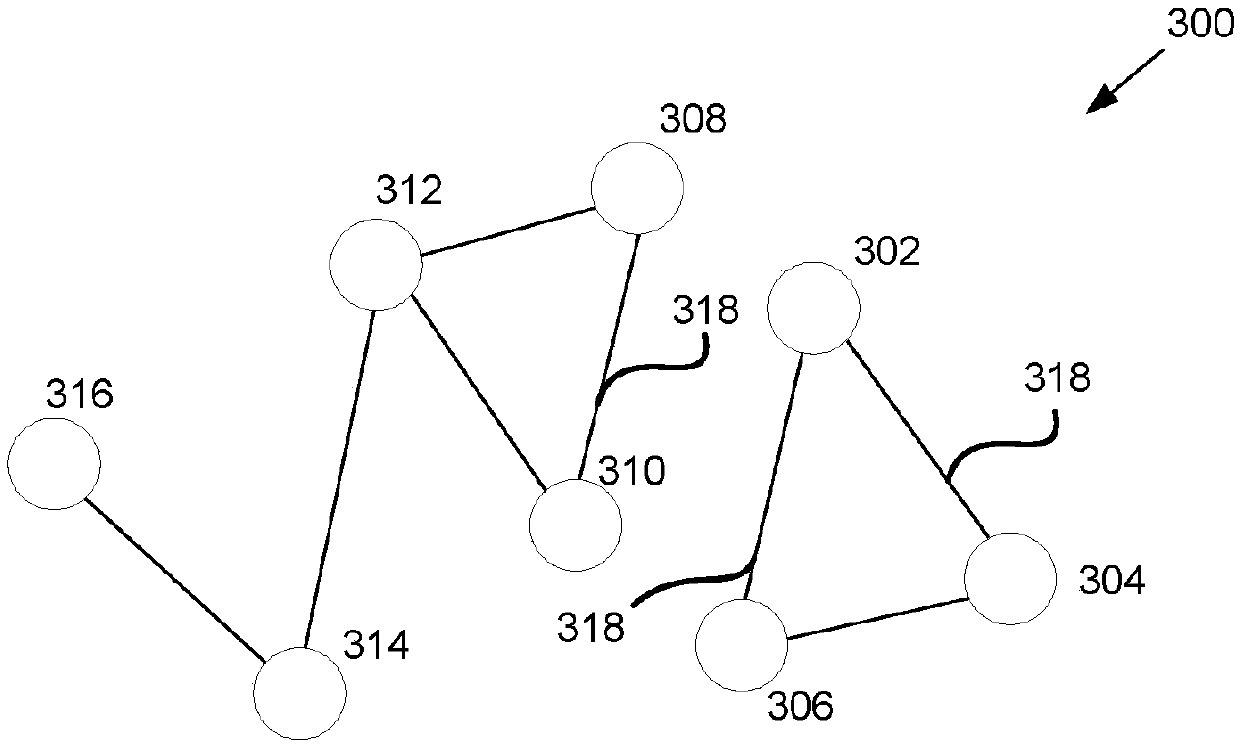
[0015] Concepts and techniques are described herein for an automated mechanism that analyzes complex service relationships within services hosted by a multi-computer infrastructure to create sub-groupings of computational entities that will allow safe and scalable actions to be performed in parallel implement. The subgroupings created ensure that even if any subgrouping of computing entities is removed from service, the multicomputer infrastructure will still have sufficient capacity to maintain uninterrupted service to customers. When scheduled separately for a service, the created subgroups maintain an orchestration of acceptable speed for any updates and / or scheduled maintenance. An easy way to get the least capacity disruption would be to work on only one compute entity at a time. For purposes of illustration, a computing entity may include a computer, a rack of computers, or other arrangement of devices operating in a coordinated fashion. At this rate, changing / updating...


PUM


Abstract

Concepts and technologies are described herein for providing an automated mechanism for grouping devices to allow safe and scalable actions to be taken in parallel. A computing device obtains data that defines service relationships between computing entities in a network of computing entities controlled by a service provider. The computing device determines two or more groups of computing entitieshaving one of a direct or indirect relationship with other computing entities within one of the two or more groups based on the obtained data. Then, the computing device determines one or more subgroups of one of the two or more groups based on the obtained data. Individual computing entities within a first subgroup of the one or more subgroups do not have a direct relationship with any of the other computing entities with the first subgroup. Output data identifying at least a portion of the subgroups is generated.

Description

Background technique [0001] Currently, when a high-impact change (eg, infrastructure maintenance) is made in a data center or any multi-computer system, it is manually scheduled. Such a system can operate many racks of computing entities (ie, computing entities) in many fault domains. When a computing entity is taken offline to perform a high-impact change or for routine maintenance, it may take many hours to complete the change / maintenance without affecting data and service operations. Manual selection of devices for servicing fails to take into account the interrelated complexity in fault domains. [0002] An easy way to get minimal capacity disruption would be to work on only one rack at a time. However, at this rate, any maintenance covering all of the racks in the 3,500-rack infrastructure could take months to complete. This approach is extremely inefficient and even impractical for use on some large systems. [0003] It is with respect to these and other consideratio...

Claims


Application Information

Patent Timeline
Patent Type & Authority Applications(China)
IPC IPC(8): H04L12/24G06Q10/06
CPCG06Q10/0631H04L41/0893H04L41/142H04L41/22H04L41/40H04L41/12
Inventor V·拉马钱德兰B·D·鲁特科夫斯基M·贾纳吉拉曼
Owner MICROSOFT TECH LICENSING LLC
Learn More