Sunproof tennis wall

A tennis and wall technology, applied to rackets, sports accessories, etc., can solve the problems of weak fixing strength, falling off the wall, reducing the application effect, etc., and achieve the effect of strong protection, prolonging service life and simple structure

Inactive Publication Date: 2018-03-06
魏英骏
View PDF1 Cites 0 Cited by
  • Summary
  • Abstract
  • Description
  • Claims
  • Application Information

AI Technical Summary

Problems solved by technology

Although this utility model has a simple structure and is easy to carry, when it is used, the entire tennis wall is fixed by a ho

Method used


Image

  • Sunproof tennis wall
  • Sunproof tennis wall
  • Sunproof tennis wall

Examples


Example Embodiment

[0050] Example 1:

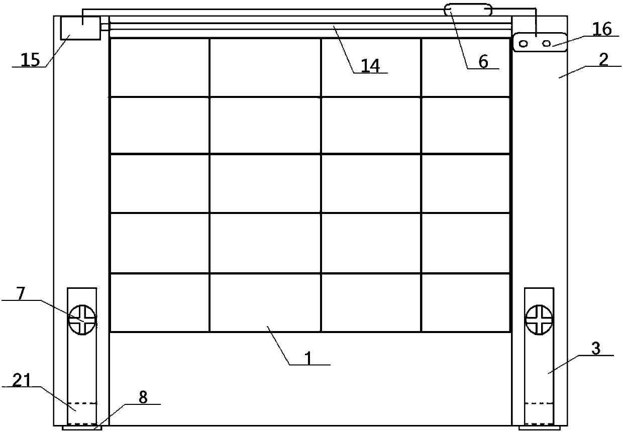
[0051] see figure 1 - Figure 8 , a sunscreen tennis wall, comprising a wall 1 and two supporting and fixing columns 2, the left and right sides of the wall 1 are respectively connected to the inner side of a supporting and fixing column 2; the top of the wall 1 A roller blind device 14 is provided, the drive shaft of the roller blind device 14 is connected to the output end of the drive motor 15, the power input end of the drive motor 15 is electrically connected to the power supply 16 through the temperature controller 6, and the drive motor 15 , temperature controller 6, power supply 16 are all arranged on the top of roller blind device 14;

[0052] The temperature controller 6 includes an insulating shell 61, an input power line 62, an output power line 63, and a temperature-sensitive metal sheet 64. The top wall of the insulating shell 61 is an open structure, including a left top wall 611, a right top wall 612 and The temperature inlet 613 between ...

Example Embodiment

[0054] Example 2:

[0055] Basic content is the same as embodiment 1, the difference is:

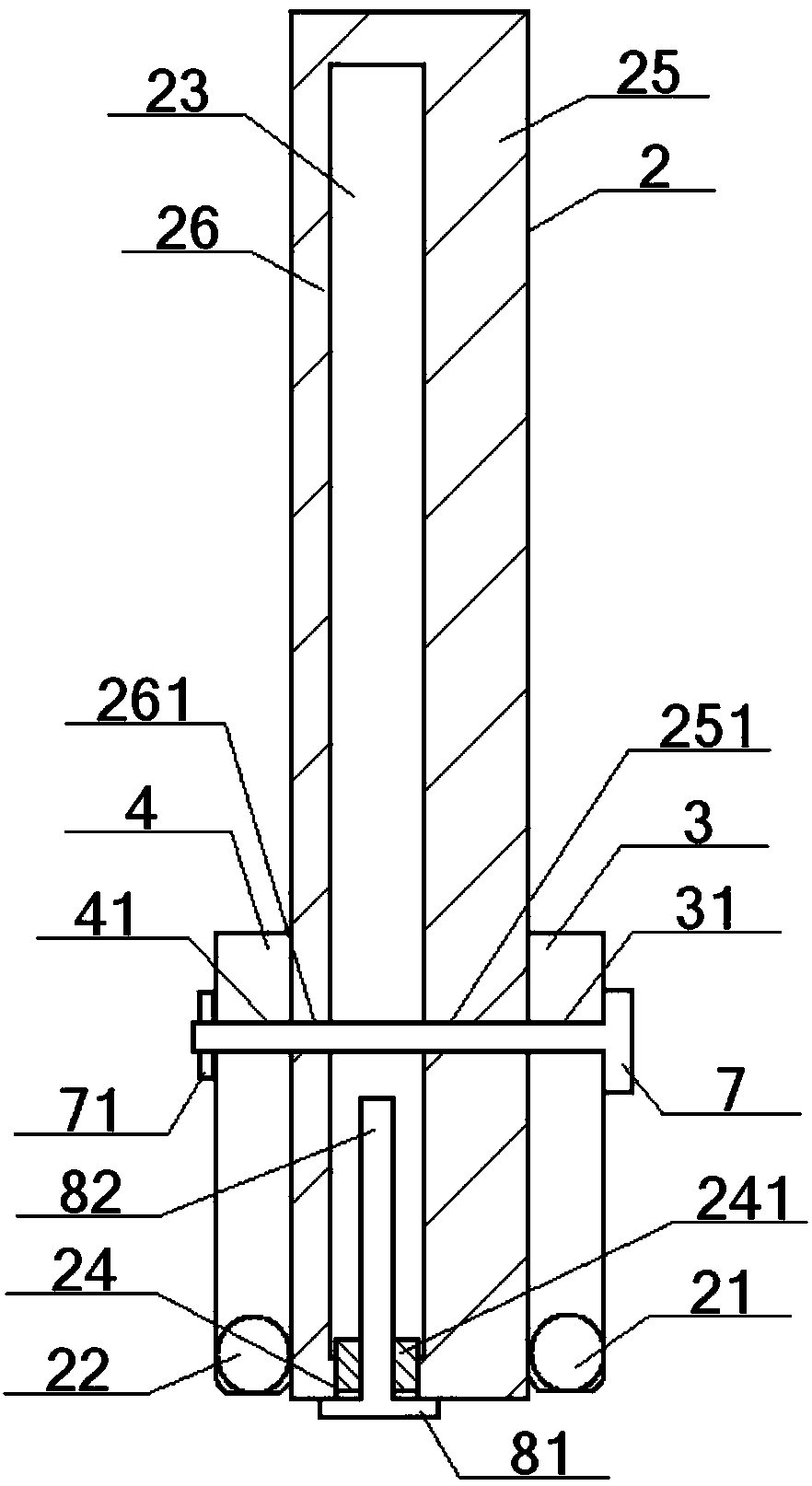
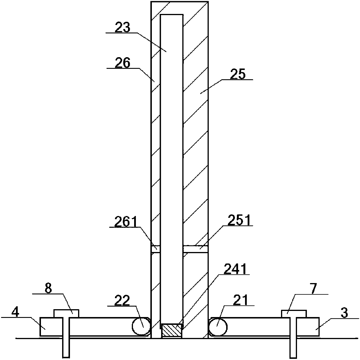
[0056] The inside of described supporting fixed column 2 offers hollow cavity 23, and the bottom of this hollow cavity 23 communicates with the closed opening 24 that supports fixed column 2 bottoms to offer, and the inside of this closed opening 24 is inlaid with closed plug 241, and the inside of closed plug 241 is connected with The No. 2 fixing bolt 8 is threaded, the bolt head 81 of the No. 2 fixing bolt 8 is flush with the bottom of the support fixing column 2, the bolt head 81 is connected with one end of the bolt column 82, and the other end of the bolt column 82 passes through in turn. The closed mouth 24 and the closed plug 241 extend to the inside of the hollow cavity 23; the positions on the front and rear sides of the hollow cavity 23 on the support and fixing column 2 are respectively the front column 25 and the rear column 26, and the front column 25 is provided with a fr...

Example Embodiment

[0058] Example 3:

[0059] Basic content is the same as embodiment 2, the difference is:

[0060] The front rotating support shaft 3 is provided with the first two fixing holes 32 at the position between the first fixing hole 31 and the front rotating shaft 21, and the rear rotating supporting shaft 4 is located at the rear fixing hole 41 and the rear rotating shaft 22. There are two rear fixing holes 42 at the position between them; the front slanting column 5 and the rear slanting column 53 are placed in the hollow cavity 23; Bottom fixing holes 51, the top of the front slanting column 5 is provided with a front top fixing hole 52 corresponding to the front wall hole 251; the bottom of the rear slanting column 53 is provided with a rear bottom fixing hole corresponding to the rear two fixing holes 42 54. A rear top fixing hole 55 corresponding to the rear wall hole 261 is opened on the top of the rear slanting column 53 .


PUM


Abstract

A sun-proof tennis wall, comprising a wall and supporting and fixing columns connected to its two sides, the roller curtain device on the top of the wall is connected to a driving motor, the driving motor is connected to a power supply through a temperature controller, and the support is fixed The front and rear sides of the column are respectively hinged with the bottom of the front and rear rotating support shafts. The No. 1 fixing bolt passes through the front fixing hole, the front side of the supporting and fixing column, the rear side of the supporting and fixing column, and the back of the rear fixing hole. It is threadedly connected with the No. 1 fixing nut, and a hollow cavity can be provided in the inside of the support fixing column to put the front slanting column and the rear slanting column on hold. This design not only has strong fixing strength, but also is easy to carry and install.

Description

technical field [0001] The invention relates to a tennis training facility, in particular to a sun-proof tennis wall, which is particularly suitable for providing a sun-proof tennis wall with strong fixing strength and easy to carry. Background technique [0002] Tennis, together with golf, bowling, and billiards, is known as the world's four major gentleman's sports. Its unique charm has long been deeply rooted in the hearts of the people. It is a sport suitable for all ages, and it is more and more loved by our people. But at present, due to the limitation of the venue, the development of tennis is hindered, especially in colleges and universities or various sports centers, the limitation of the venue has become the biggest obstacle restricting the development of tennis. For this reason, tennis walls have appeared to alleviate the limitation of the venue. The tennis wall generally includes the wall and the supporting columns connected on both sides. When in use, the athlet...

Claims


Application Information

Patent Timeline
IPC IPC(8): A63B69/38
CPCA63B69/38A63B69/0097A63B2102/02A63B2220/72A63B2220/833A63B2225/30
Inventor 魏英骏
Owner 魏英骏
Why Eureka
Try Eureka