
Multi-cone, multi-stage spray nozzle

A technology for spray nozzles and nozzles, which is applied to spray devices, spray devices, lighting and heating equipment, etc., and can solve problems such as limited adjustability

Pending Publication Date: 2018-03-06
FISHER CONTROLS INT LLC
View PDF12 Cites 2 Cited by
  • Summary
  • Abstract
  • Description
  • Claims
  • Application Information

AI Technical Summary

Problems solved by technology

But the adjustability of these control variables can be limited based on the structure of the nozzle itself

Method used


Image

  • Multi-cone, multi-stage spray nozzle
  • Multi-cone, multi-stage spray nozzle
  • Multi-cone, multi-stage spray nozzle

Examples


Embodiment Construction

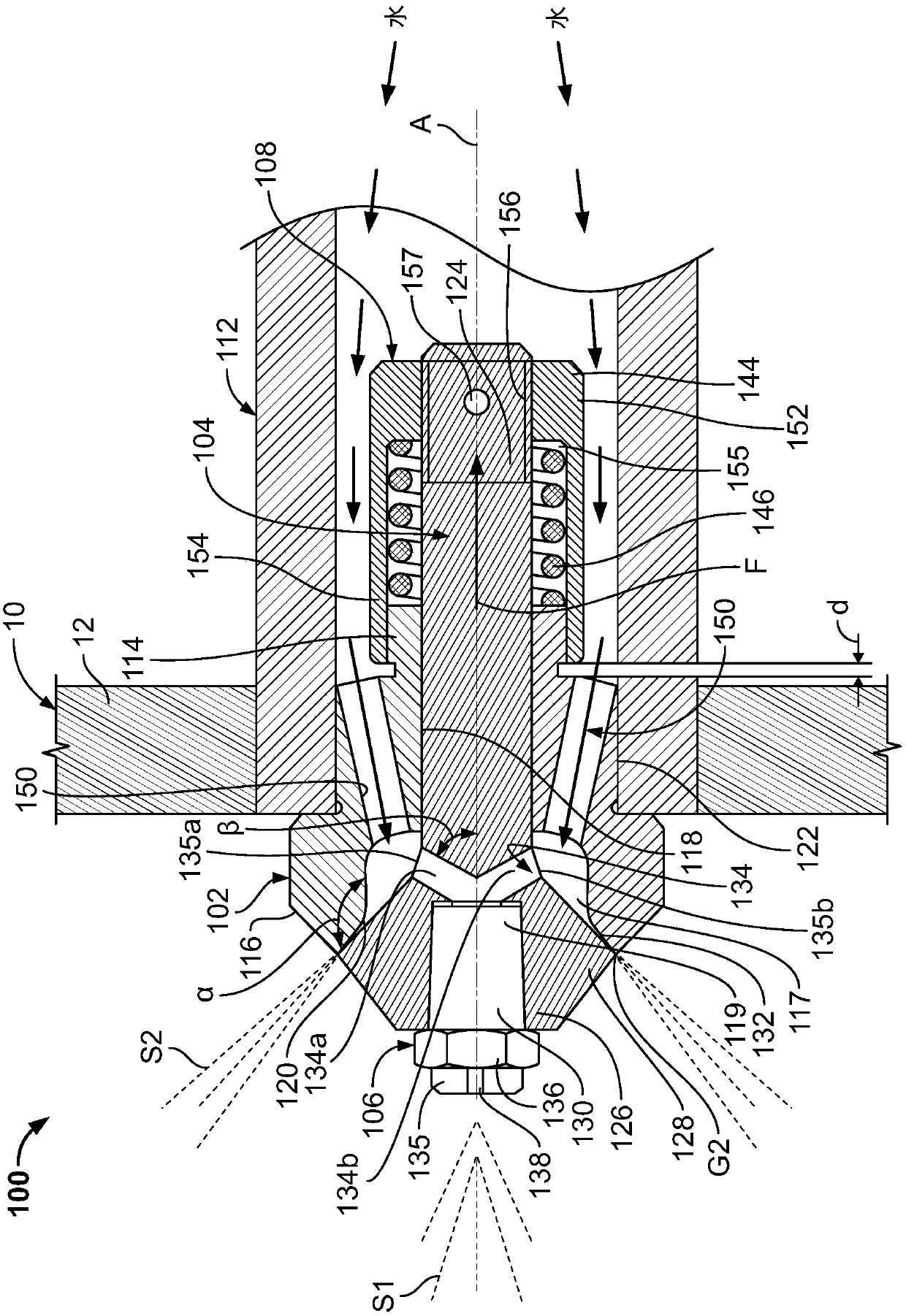
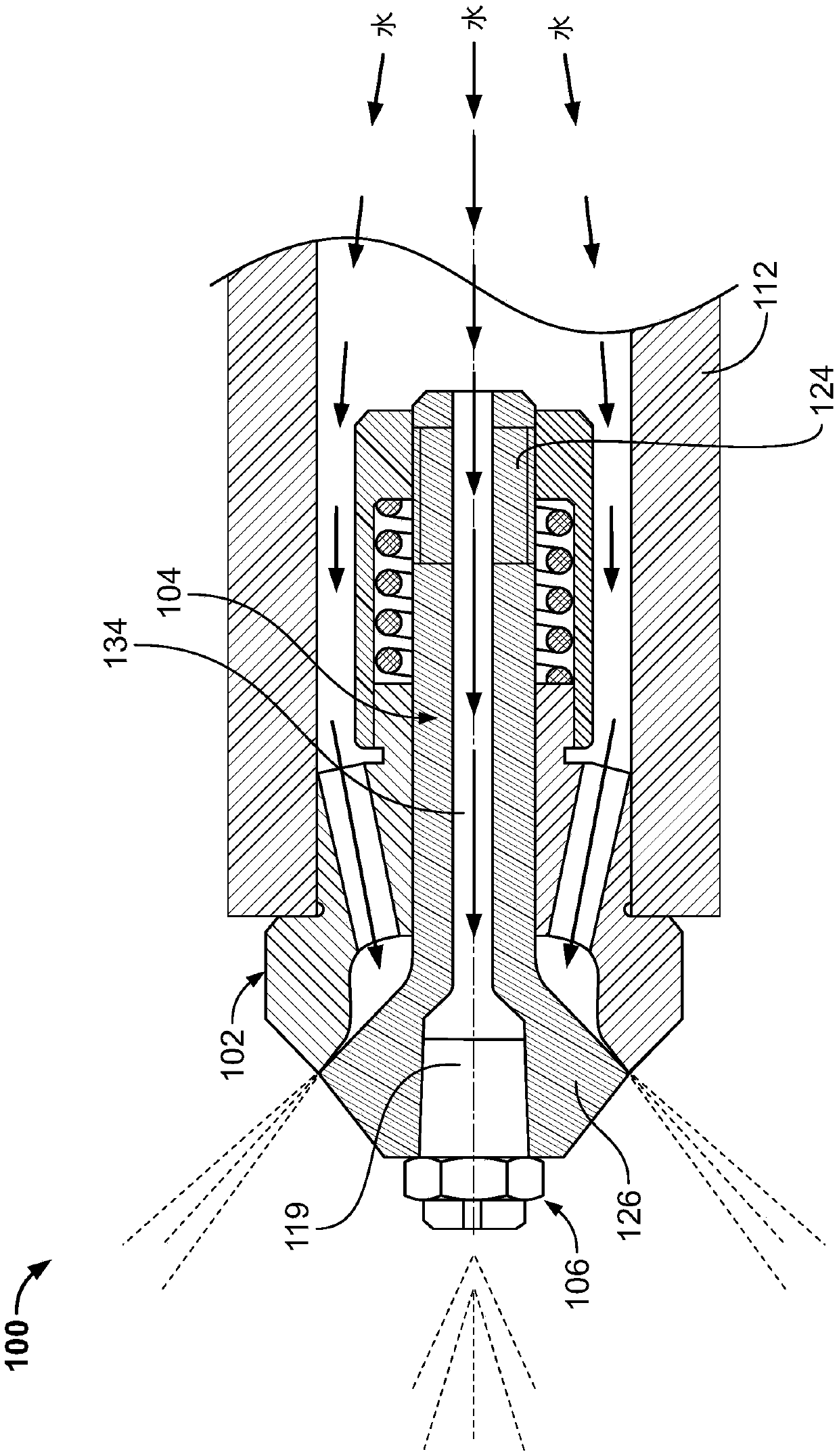
[0018] The present disclosure is directed to an injection nozzle typically used in steam conditioning applications such as desuperheaters and steam conditioning valves, although other applications are contemplated. In disclosed embodiments, the spray nozzle includes two or more stages of operation for accommodating an increasing range of cooling fluid operating pressures and flow rates through the nozzle. Two or more stages are achieved by implementing two or more valve heads with different operating sensitivities.

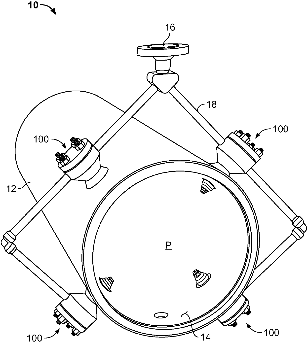
[0019] figure 1 Depicted is a steam tube 10 comprising a plurality of injection nozzles 100 constructed in accordance with the present disclosure. Generally, steam pipe 10 may be used to reduce the temperature of superheated steam traveling therein to a desired set point temperature. For example only, figure 1 The steam pipe 10 can be a desuperheater (for example, TBX-T desuperheater, TBX desuperheater, DMA / AF desuperheater, or DMA / AF-HTC desuperheater)...


PUM


Abstract

A multi-cone, multi-stage spray nozzle includes a nozzle body, a valve stem with a first valve head, and a second valve head attached to the first valve head. The first valve stem is biased into a closed position against a valve seat of the nozzle body by a bias device. The second valve head is continuously open. Upon the application of a first fluid pressure, which is less than a threshold fluidpressure, the bias device maintains the valve stem in the closed position while the second valve head is continuously open. And upon the application of a second fluid pressure, which is at least as great as the threshold fluid pressure, the valve stem moves to an open position while the second valve head remains continuously open.

Description

technical field [0001] The present disclosure relates to spray nozzles, and more particularly, to spray nozzles for steam conditioning equipment such as desuperheaters and steam conditioning valves. Background technique [0002] Steam conditioning devices, such as desuperheaters and steam conditioning valves, are used in many industrial fluid and gas lines to reduce the temperature of superheated process fluids and gases to a desired set point temperature. For example, desuperheaters are used in the power process industry to cool superheated steam. Desuperheaters use nozzles to inject a fine spray of atomized cooling water or other fluid (which may be referred to as a spray cloud) into the steam pipe through which the process steam flows. Evaporation of the water droplets in the spray cloud reduces the temperature of the process steam. The resulting temperature drop can be controlled by adjusting the characteristics of the spray cloud by adjusting one or more control varia...

Claims


Application Information

Patent Timeline
Patent Type & Authority Applications(China)
IPC IPC(8): F28C3/08F22G5/12B05B1/30
CPCB05B1/3006F22G5/123F28C3/08B05B1/304B05B1/323F22G5/126B05B1/14B05B1/30B05B1/32F22G5/12B05B1/1609B05B1/16B01F23/21321B01F2101/48
Inventor 邱彦J·P·古德温
Owner FISHER CONTROLS INT LLC
Learn More