Fan as well as air outlet control method, device and system thereof

A control method and fan technology, applied in pump control, non-variable displacement pump, machine/engine, etc., can solve the problem of low user comfort and achieve the effect of high comfort

Inactive Publication Date: 2018-03-09
GREE ELECTRIC APPLIANCES INC
View PDF6 Cites 17 Cited by
  • Summary
  • Abstract
  • Description
  • Claims
  • Application Information

AI Technical Summary

Problems solved by technology

[0005] Embodiments of the present invention provide a fan and its air outlet control method, device, and system to at least solve the technical problem in the prior art that the fan intelligently only sends air according to a predetermined gear, resulting in low user comfort

Method used


Image

  • Fan as well as air outlet control method, device and system thereof
  • Fan as well as air outlet control method, device and system thereof
  • Fan as well as air outlet control method, device and system thereof

Examples


Embodiment 1

[0026] According to an embodiment of the present invention, an embodiment of a fan air outlet control method is provided. It should be noted that the steps shown in the flow charts of the accompanying drawings can be executed in a computer system such as a set of computer-executable instructions, Also, although a logical order is shown in the flowcharts, in some cases the steps shown or described may be performed in an order different from that shown or described herein.

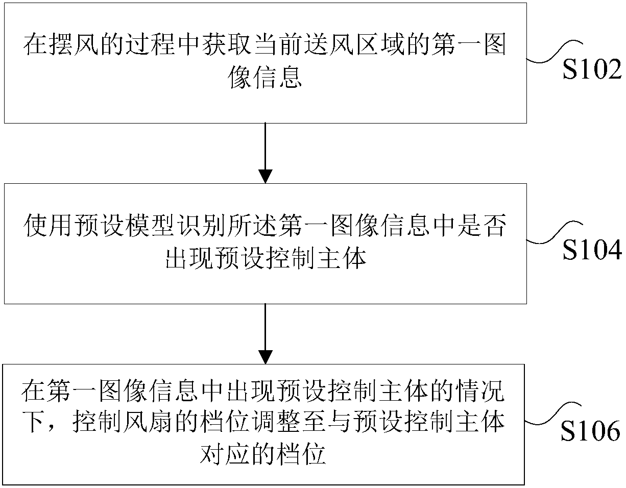
[0027] figure 1 It is a flow chart of a method for controlling the air outlet of a fan according to an embodiment of the present invention, such as figure 1 As shown, the method includes the following steps:

[0028] Step S102, acquiring the first image information of the current blowing area during the swinging process.

[0029] Specifically, swing wind is used to refer to the fan to adjust the air supply area of ​​the fan by swinging the head or by other means. The wind swing method can be to control the...

Embodiment 2

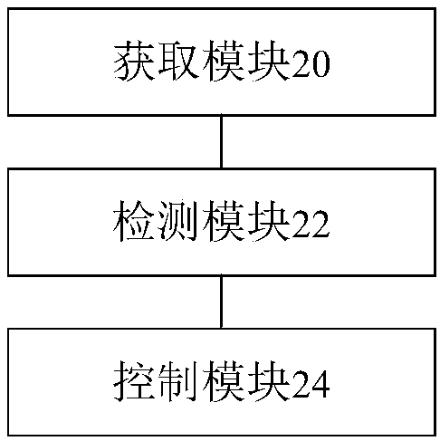
[0066] According to an embodiment of the present invention, an embodiment of an air outlet control device for a fan is provided, figure 2 is a schematic diagram of a fan air outlet control device according to an embodiment of the present invention, such as figure 2 As shown, the device includes:

[0067] The acquiring module 20 is configured to acquire the first image information of the current blowing area during the swinging process.

[0068] The detection module 22 is configured to use a preset model to identify whether a preset control subject appears in the first image information, wherein the preset control subject has a corresponding gear position, and the preset model is obtained through machine learning based on multiple sets of sample data, and the sample data Including: image information containing the control subject and a label for indicating whether the control subject in the image information is a preset control subject.

[0069] The control module 24 is con...

Embodiment 3

[0071] According to an embodiment of the present invention, a storage medium is provided, and the storage medium includes a stored program, wherein when the program is running, the device where the storage medium is located is controlled to execute any one of the fan air control methods in Embodiment 1.


PUM


Abstract

The invention discloses a fan as well as an air outlet control method, device and system thereof. The method comprises steps as follows: first image information of a current air supply area is acquired in a swing process; whether a preset control subject appears in the first image information is recognized by a preset model, wherein the preset control subject has a corresponding gear, the preset module is obtained through machine learning according to multiple groups of sample data, and the sample data comprises image information containing a control subject and a label for indicating whetherthe control subject in the image information is the preset control subject; under the condition that the preset control subject appears in the first image information, the gear of the fan is controlled to be adjusted to the gear corresponding to the preset control subject. The technical problem of low comfort level of a user due to the fact that a fan can only supply air according to the preset gear in the prior art is solved.

Description

technical field [0001] The present invention relates to the field of fans, in particular, to a fan and its air outlet control method, device and system. Background technique [0002] At present, the control method of the fan is still realized by the user directly controlling the gears. Usually, the fan has three gears, corresponding to different speeds, so as to generate different air volumes. While controlling the air volume, the fan also has a pendulum function. Wind function, that is, to adjust the direction of fan blowing to change the blowing area. That is to say, the functions that the fan can realize at present are mainly to swing the air and control the air volume. [0003] However, usually there are multiple users using the same fan in one scene, and each user may have different air volume requirements, and the current fan control method cannot meet the needs of multiple users in the same scene. [0004] Aiming at the problem in the prior art that the fan intellig...

Claims


Application Information

Patent Timeline
Patent Type & Authority Applications(China)
IPC IPC(8): F04D27/00
CPCF04D27/007F04D27/004
Inventor 陈嘉琪张君明敬仕林杨昆庞凤山邬祥俊朱小平郭芷旗
Owner GREE ELECTRIC APPLIANCES INC
Why Eureka
Try Eureka