[0038] Example
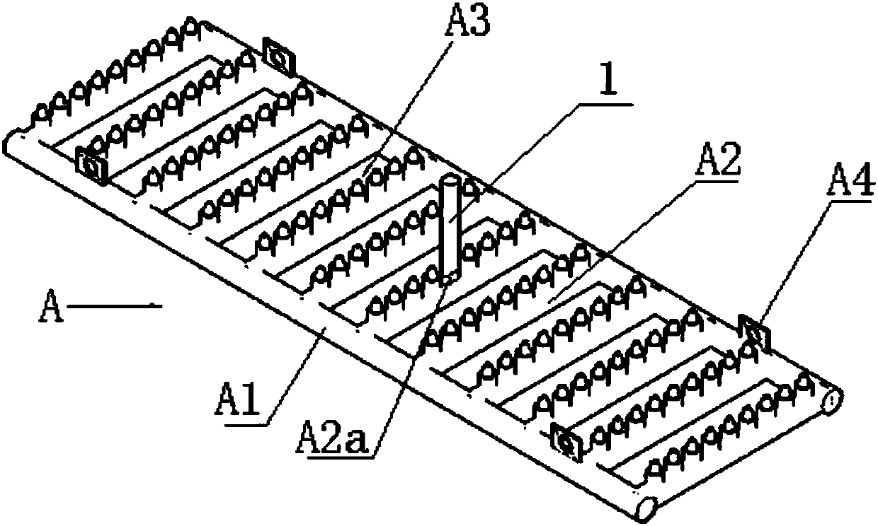
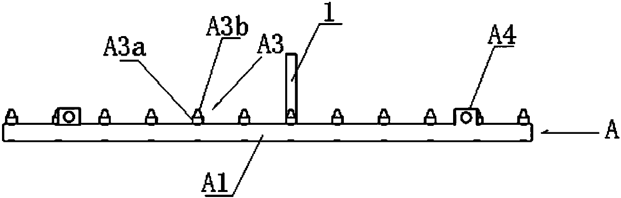
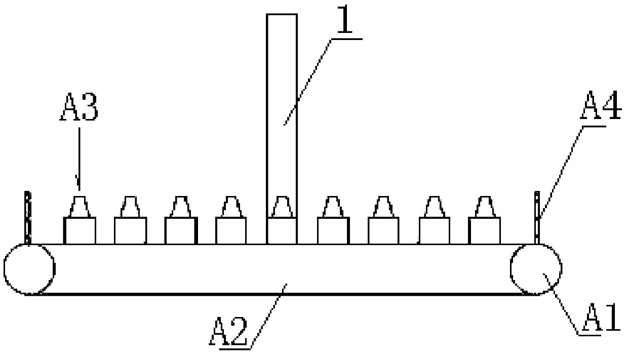
[0039] Such as Figure 1 ~ Figure 3 As shown, the grid-type gas disturbance estuary mud dredging device includes an air inlet pipe 1, which is arranged at the center of a grid-type gas disturbance assembly A and is connected to the internal pipeline of the grid type gas disturbance assembly Connected, the external air supply component passes compressed air into the pipe of the grid-type gas disturbance component through the intake pipe, and then sprays it from each nozzle set on the grid-type gas disturbance component to disturb the dredging of the floating mud in the estuary.
[0040] The grid-type gas disturbance component A includes a rectangular pipe A1, a transverse pipe A2, a nozzle group A3, and a hanging ring A4 for hoisting. Among them, the rectangular pipe is horizontally arranged in the middle area surrounded by the pipe and has 10 to 14 at equal intervals. Horizontal pipeline (10 horizontal pipelines in this embodiment), the two ends of the horizontal pipeline communicate with the rectangular pipeline, and the entire rectangular pipeline is divided into 12 to 16 equally spaced grid-shaped air jet pipelines (in this embodiment There are 12 air-jet lines), and all the lines are connected, and the nozzle group is set on each air-jet line. The air inlet line 1 is connected to the center of the horizontal pipe located in the middle of the rectangular pipe through a quick connector. The air hole A2a passes compressed air into each jet pipeline, and then simultaneously ejects from each nozzle group to disturb the dredging of the estuary floating mud. There are 2 to 3 pairs of hanging rings A4 for hoisting (in this example, there are 2 pairs). ), are arranged on the outer tube body of the rectangular pipeline in two-to-two opposing manner, and the hoisting ring is connected with the ship hoisting steel cable, and the entire grid-type gas disturbance assembly is placed in or hoisted out of the river.
[0041] The nozzle group A3 includes 8 to 10 air jet bases A3a and air nozzles A3b (9 air jet bases and air nozzles in this embodiment), wherein the air jet bases are welded at equal intervals on the air jet pipeline, and the air nozzles are threaded The connection method is screwed on the jet base.
[0042] The jet nozzle A3b can be replaced by a non-ventilated jet plug, which is screwed on the jet base to close the jet function and adjust the gas vortex intensity.
[0043] The grid-type gas disturbance estuary floating mud dredging device of the present invention has its disturbance capability determined by the gas nozzle aperture, the number of gas nozzles, the gas nozzle arrangement, gas pressure, and gas flow. The gas can be adjusted arbitrarily by adjusting the nozzle or partial blocking Whirl strength.
[0044] The estuary floating mud dredging method is based on the grid-type gas-disturbed estuary floating mud dredging device. The specific steps are as follows:
[0045] 1) Assemble the grid type gas disturbance component A:
[0046] Rectangular pipe A1 and transverse pipe A2 form 12-16 grid-shaped jet pipelines at equal intervals. The jet nozzle A3b of the nozzle group A3 is screwed to each jet base A3a. When the gas turbulence intensity needs to be adjusted , Replace part of the air nozzle with a non-ventilated air nozzle to block;
[0047] 2) Connection of external gas supply component and grid type gas disturbance component A:
[0048] Connect the air compressor to the air inlet pipe 1, and the air inlet pipe is connected to the central air inlet hole A2a of the transverse pipe A2 located in the middle of the rectangular pipe A1 through the quick connector. At this time, the air compressor is turned on and the compressed air is injected for air injection. Test and monitor the pressure through an external air pressure gauge, and turn off the air compressor after confirming normal operation;
[0049] 3) Connection operation between grid type gas disturbance component A and engineering ship:
[0050] The entire grid-type gas disturbance component adopts engineering ship to realize transportation positioning-the grid-type gas disturbance component is placed on the deck and transported to the predetermined dredging site, and the towline is arranged on the engineering ship, and one end of the towline is connected to the bollard on the engineering ship Connected, the other end is connected with the end of the grid-type gas disturbance component;
[0051] 4) Connection operation between grid-type gas disturbance component A and ship hoisting steel cable:
[0052] Use hoisting device to arrange ship hoisting steel cable, one end of the ship hoisting steel cable is connected with the hoisting device, and the other end is connected with the hoisting ring A4 of the grid-type gas disturbance component by D-shaped or bow shackle;
[0053] 5) Water dredging operation of grid gas disturbance assembly A:
[0054] The hoisting device lifts the entire grid-type gas disturbance assembly through the ship hoisting steel cables, placing them in parallel into the water, confirming that the water reaches the bottom, setting the pressure gas parameters, turning on the external air compressor to deliver compressed air, and observing the bubbles on the water surface. Confirm that the gas transmission is normal, start the engineering ship, and drag the grid-type gas disturbance assembly through the towline for dredging operations. At this time, the compressed air is delivered to each group of nozzle groups A3 through the intake pipe 1, the rectangular pipe A1 and the horizontal pipe A2. The jet nozzle A3b outputs high-pressure gas to disturb the surrounding silt-containing water body, causing the fine-grained silt in the shallow surface layer of the river channel and river bed to hang up, and the high-silt content water body located in the lower part of the shallow surface layer will also follow the vertical direction of the water body. Distribute and transport, and evenly distribute along with the flow direction of the river, dredging the river, after the operation is over, turn off the air compressor, relax the traction rope, and lift the grid-type gas disturbance component to the deck through the lifting device for the next operation .
[0055] The grid-type gas disturbance component A in steps 1) to 5) can be assembled and used in parallel according to the width of the river or the distribution of the floating mud that needs to be dredged. The grid-type gas can also be adjusted as needed. The length or width of the rectangular pipe A1 and the transverse pipe A2 of the disturbance assembly and the number of nozzle groups A3.
[0056] The grid type gas disturbance estuary floating mud dredging device and the estuary floating mud dredging method of the present invention provide a dredging tool and a supporting dredging method suitable for estuary floating mud or new silt. By delivering high-pressure gas into the floating mud, Stirring the fine-grained sand at the bottom to the middle and upper water bodies interferes with the process of silting and gradual compaction of new silt and floating mud on the bed surface, changing the vertical density distribution of sandy water bodies, and greatly extending the sandy water bodies The transport distance of the middle sediment by the tide relieves the pressure of insufficient navigable water depth caused by the back siltation of the channel; the grid-type gas disturbance estuary floating mud dredging device and the estuary floating mud dredging method of the present invention greatly reduce the energy of the existing channel dredging technology Cost-consuming.