Novel rotating mold base

A technology of rotating frame and mold base, which is applied in the direction of tool storage device, manufacturing tools, etc., can solve the problems of easy accidents, heavy mold weight, troubles, etc., and achieve the effect of meeting the needs of use, reducing danger and being convenient to use

Active Publication Date: 2018-03-23
MEIBAN TECH ZHONGSHAN CO LTD
View PDF7 Cites 7 Cited by
  • Summary
  • Abstract
  • Description
  • Claims
  • Application Information

AI Technical Summary

Problems solved by technology

[0002] Most of the existing mold racks are vertical racks. If the molds inside need to be used, they need to be taken out by hand or electric forklift. The process is very troublesome, because most of the molds are very heavy. If it cannot be moved, it is very easy to cause accidents when using forklifts and other tools to take it out. Accidents due to being smashed by molds abound, which is very dangerous and very inconvenient

Method used


Image

  • Novel rotating mold base
  • Novel rotating mold base
  • Novel rotating mold base

Examples


Embodiment Construction

[0017] The present invention will be further described below in conjunction with accompanying drawing description and specific embodiment:

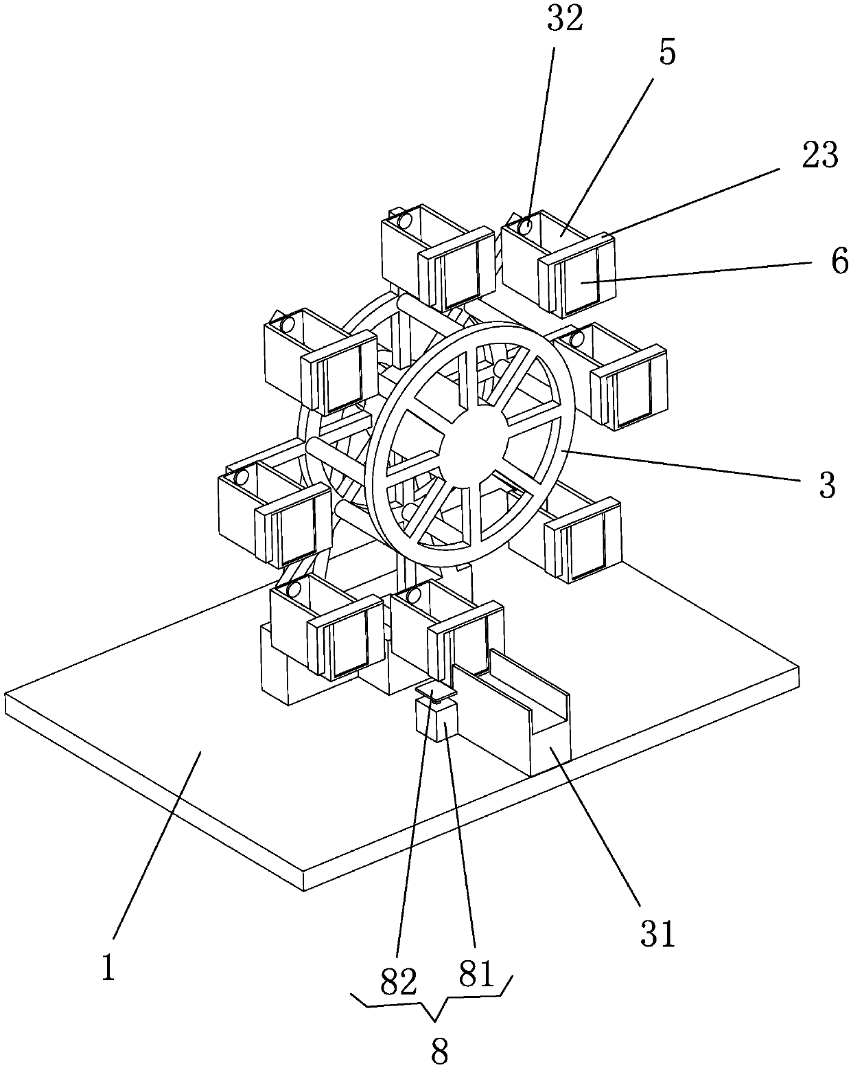
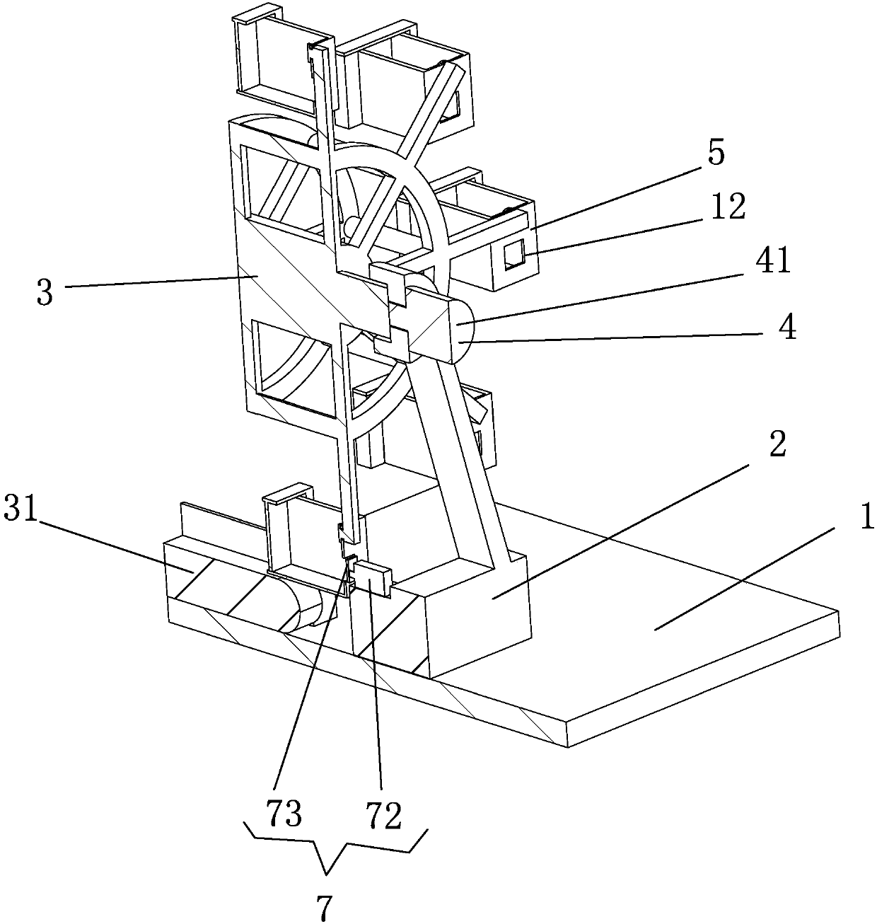
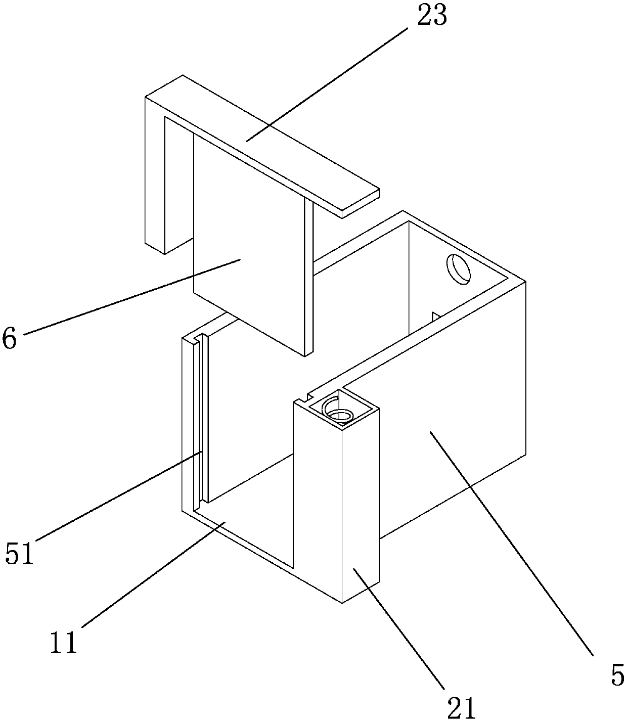
[0018] Such as Figures 1 to 4 A new type of rotating formwork shown includes a base plate 1, a support frame 2 is provided above the base plate 1, a rotating frame 3 is provided in front of the support frame 2, and a power frame is provided behind the support frame 2. The rotating mechanism 4 that drives the rotating frame 3 to rotate, on the rotating frame 3, a plurality of mounting frames 5 capable of holding molds are distributed on the rotating shaft 32 at circumferential intervals, and the front end of the mounting frame 5 is a through groove 11. A baffle plate 6 is provided on the through groove 11, and a lifting mechanism 8 that can lift the baffle plate 6 on the lowermost bearing frame 5 is provided on the bottom plate 1 below the rotating frame 3, and a lifting mechanism 8 that can lift the baffle plate 6 on the lowermost bearin...


PUM


Abstract

The invention discloses a novel rotating mold base which comprises a bottom plate. A supporting frame is arranged above the bottom plate. A rotating frame is arranged in front of the supporting frame.A rotating mechanism is arranged behind the supporting frame. A plurality of loading boxes are circumferentially distributed on the rotating frame at intervals through corresponding rotating shafts.Through grooves are formed in the front ends of the loading boxes and are further provided with corresponding baffles. A lifting mechanism is arranged on the bottom plate and located below the rotating frame. Notches are formed in the rear end wall surfaces of the loading boxes. A pushing-out mechanism is arranged below the supporting frame and corresponds to the notch of the loading box at the bottommost position. The novel rotating mold base is simple in structure and convenient to use, and the rotating frame can be driven to rotate through the rotating mechanism. The loading boxes are affected by gravity when being filled with molds, and thus can be kept to move horizontally all the time, the loading boxes of the required molds can be horizontally rotated to the position of the pushing-out mechanism, and the lifting mechanism is controlled to push out the molds after the baffles are jacked up. In this way, the problem of manpower or forklift carrying is effectively solved, the dangerousness is greatly reduced and the safety guarantee is brought about to mechanical workers.

Description

technical field [0001] The invention relates to the field of formwork, in particular to a novel rotating formwork. Background technique [0002] Most of the existing mold racks are vertical racks. When the molds inside need to be used, they need to be taken out by hand or electric forklift. The process is very troublesome, because most of the molds are very heavy. If it cannot be moved, it is very easy to cause accidents when using tools such as forklifts to take it out. Accidents due to being smashed by molds abound, which is very dangerous and very inconvenient. [0003] Therefore, the existing mold frame needs to be further improved. Contents of the invention [0004] The purpose of the present invention is to provide a novel rotary formwork in order to overcome the deficiencies in the prior art. [0005] A new type of rotary formwork, including a base plate, characterized in that a support frame is provided above the base plate, a rotating frame is provided in front ...

Claims


Application Information

Patent Timeline
Patent Type & Authority Applications(China)
IPC IPC(8): B25H3/00
CPCB25H3/00
Inventor 林顺德徐富金郑明山魏明明蔡齐挺
Owner MEIBAN TECH ZHONGSHAN CO LTD
Why Eureka
Try Eureka