Supercharge Your Innovation With Domain-Expert AI Agents!

Oil tank transporting and installing integrated device

A technology of oil tanks and lifting devices, which is applied in the directions of transportation and packaging, hoisting devices, lifting equipment braking devices, etc. It can solve the problems of large volume, vertical hoisting of the bridge crane in the main factory building, and no installation conditions for oil tank equipment, etc. problems, to achieve the effect of simple operation, no safety risk, and fast construction progress

Pending Publication Date: 2018-03-23
SINOHYDRO BUREAU 5
View PDF0 Cites 0 Cited by
  • Summary
  • Abstract
  • Description
  • Claims
  • Application Information

AI Technical Summary

Problems solved by technology

[0002] At present, many underground plants are limited by space, construction schedule and hoisting equipment; the turbine oil depot in the early stage needs to be used as a temporary construction passage for the underground plant and does not have the conditions for the installation of oil tank equipment, and the oil tank cannot be installed after the main concrete construction of the follow-up plant is completed. Use the bridge crane in the main workshop to erect and hoist in place; the oil tanks that are large and can only be transported horizontally to the site do not have the ability to turn over, place, and install in the oil depot with limited height and space, so that the construction must require corresponding auxiliary tooling. Satisfy

Method used


Image

  • Oil tank transporting and installing integrated device
  • Oil tank transporting and installing integrated device
  • Oil tank transporting and installing integrated device

Examples


Embodiment Construction

[0020] The present invention will be further described below in conjunction with the accompanying drawings and specific embodiments.

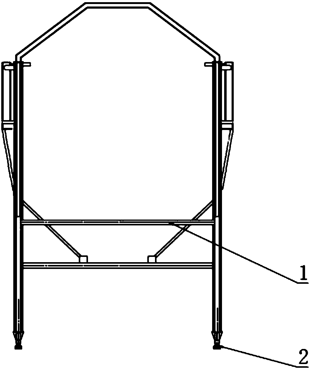
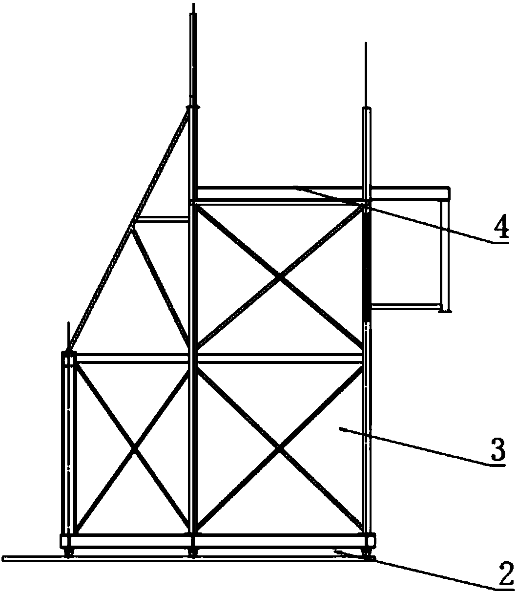
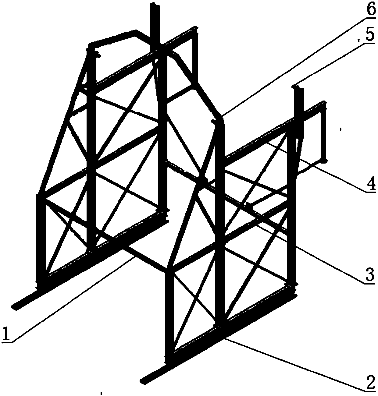
[0021] Such as Figure 1-3 As shown, an integrated device for oil tank transportation and installation includes a horizontal moving device 2, a door frame 3 and a sliding device 4; the door frame 3 rolls along the horizontal moving device 2; the horizontal moving device 2 includes Centerline direction, two tracks matched with the width of the door frame 3 and a rolling device arranged on the door frame 3 that can roll along the tracks; the sliding device 4 includes two slide rails arranged on the top of the door frame 3 along the direction of the tracks and can Disassemble the two symmetrical shafts arranged in the oil tank circumferential direction; the two shafts are respectively matched with the two slide rails; the door frame 3 is provided with a lifting device, and the lifting device includes a front-end lifting device 6 corresponding to t...


PUM


Abstract

The invention discloses an oil tank transporting and installing integrated device. The oil tank transporting and installing integrated device comprises a horizontal movement device, a door frame and asliding device. The door frame rolls along the horizontal movement device. The sliding device comprises two sliding rails arranged at the upper portion of the door frame in the track direction, and two shaft rods detachably and symmetrically arranged on an oil tank in the circumferential direction. The two shaft rods are matched with the two sliding rails correspondingly. The door frame is provided with a lifting device. The lifting device comprises a front end lifting device corresponding to the front end of the oil tank, a rear end lifting device corresponding to the rear end of the oil tank, and two flying rings symmetrically arranged at the bottom of the oil tank in the circumferential direction. The flying rings are connected with the front end lifting device and the rear end liftingdevice correspondingly. The front end lifting device is used for dragging the oil tank to slide forwards along the sliding rails. The rear end lifting device is used for dragging the oil tank to downwards rotate. By means of the oil tank transporting and installing integrated device, the installing problems about vertical overturning, horizontal transporting, hoisting in place and the like of thelarge turbine oil tank transported in a lying manner under influences from the limited space, limited hoisting equipment and the construction schedule arrangement can be solved.

Description

technical field [0001] The invention relates to an integrated device for transporting and installing an oil tank. Background technique [0002] At present, many underground plants are limited by space, construction schedule and hoisting equipment; the turbine oil depot in the early stage needs to be used as a temporary construction passage for the underground plant and does not have the conditions for the installation of oil tank equipment, and the oil tank cannot be installed after the main concrete construction of the follow-up plant is completed. Use the bridge crane in the main workshop to erect and hoist in place; the oil tanks that are large and can only be transported horizontally to the site do not have the ability to turn over, place, and install in the oil depot with limited height and space, so that the construction must require corresponding auxiliary tooling. satisfy. Contents of the invention [0003] The invention provides an integrated device for transport...

Claims


Application Information

Patent Timeline
Patent Type & Authority Applications(China)
IPC IPC(8): B66C25/00B66C5/02
CPCB66C5/02B66C25/00
Inventor 陈林肖明
Owner SINOHYDRO BUREAU 5
Features
  • R&D
  • Intellectual Property
  • Life Sciences
  • Materials
  • Tech Scout
  • Unparalleled Data Quality
  • Higher Quality Content
  • 60% Fewer Hallucinations
Learn More