Split cycloid disc numerical-control milling and positioning clamp

A technology of CNC milling and positioning fixture, applied in positioning devices, clamping, manufacturing tools, etc., can solve the problems of high positioning requirements for split cycloid disk processing, and achieve simple and reliable positioning methods, simple positioning methods, and neutrality. Good results

Active Publication Date: 2014-07-23
JIANGSU TAILONG MACHINERY GRP CO CO LTD
View PDF6 Cites 1 Cited by
  • Summary
  • Abstract
  • Description
  • Claims
  • Application Information

AI Technical Summary

Problems solved by technology

The split cycloidal disc is convenient for subsequent processes such as surface quenching and grinding of the cycloidal tooth surfaces of the inner and outer split di

Method used


Image

  • Split cycloid disc numerical-control milling and positioning clamp
  • Split cycloid disc numerical-control milling and positioning clamp
  • Split cycloid disc numerical-control milling and positioning clamp

Examples


Embodiment Construction

[0018] Below in conjunction with accompanying drawing, the specific embodiment of the present invention is described in further detail:

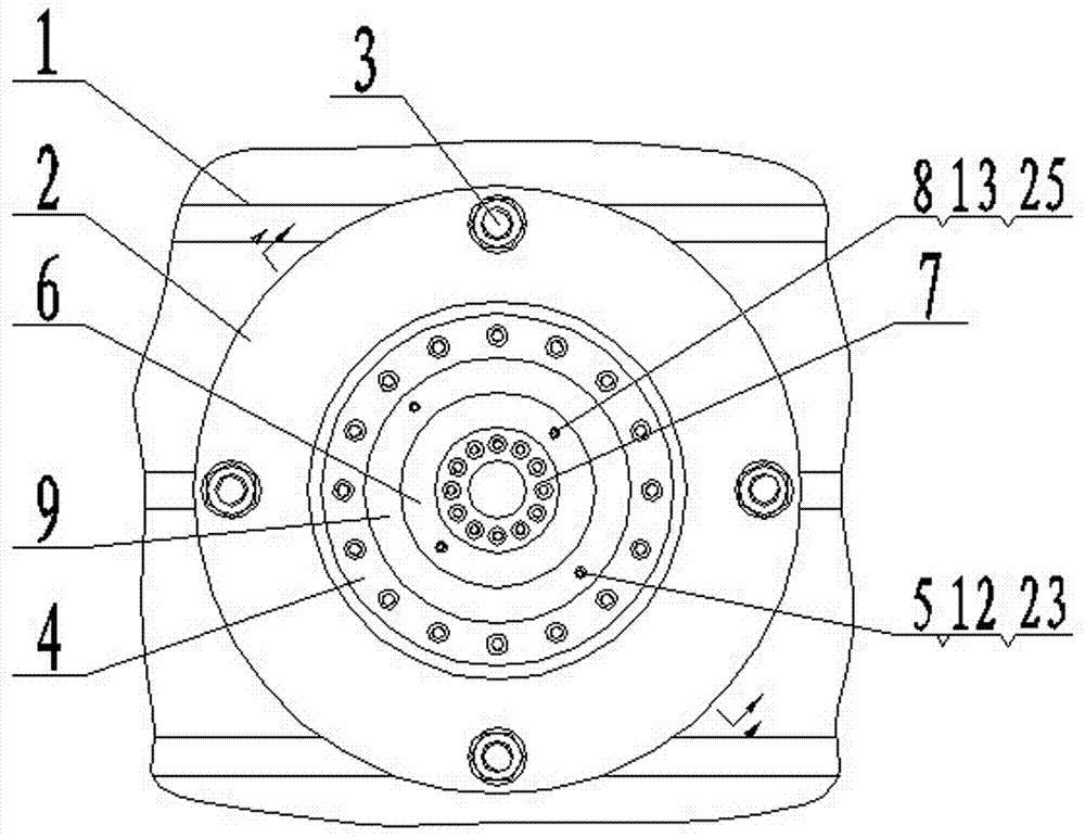
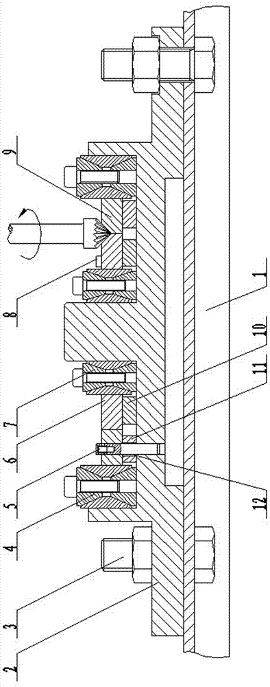
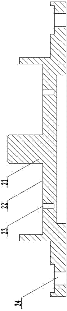
[0019] As shown in the figure, a split-type cycloidal disc CNC milling positioning fixture includes a mold 2, a bolt 3, an outer expansion sleeve 4, an outer cylindrical pin 5, an inner expansion sleeve 7, an inner cylindrical pin 8, an inner shim 10 and an outer Parallel iron 11, the center of the mold 2 is provided with a coaxial cylindrical boss 21 and a circular groove 22, the outer circumference of the cylindrical boss 21 is coaxially sleeved with an inner expansion sleeve 7, and the inner expansion sleeve 7 The circumference cooperates with the outer circumference of the cylindrical boss 21, and an outer expansion sleeve 4 is also provided in the annular groove 22. The outer circumference of the outer expansion sleeve 4 cooperates with the inner circumference of the annular groove 22, and the inner circumference of the outer exp...


PUM


Abstract

The invention relates to a split cycloid disc numerical-control milling and positioning clamp which comprises a mold, an inner expansion sleeve, an outer expansion sleeve and bolts. The center of the mold is provided with a circular-ring-shaped groove and a cylindrical boss, wherein the circular-ring-shaped groove and the cylindrical boss share the same axis. The outer circumferential face of the cylindrical boss is coaxially connected with the inner expansion sleeve in a sleeved mode, and the inner circumferential face of the circular-ring-shaped groove is coaxially connected with the outer expansion sleeve. The outer edge of the mold is provided with two or more sets of bolt holes, and the bolts connected with T-shaped tables of a numerical-control milling machine are arranged in the bolt holes. The features that the expansion sleeves are good in centering performance and large in expanding force are utilized, the inner expansion sleeve and the outer expansion sleeve are used for being matched with the cylindrical boss and the circular-ring-shaped groove respectively to position an inner split disc and an outer split disc, the positioning manner is simple, accurate and reliable, after a cylindrical pin is used for being matched with a mold cylindrical pin hole to circumferentially position the inner split disc and the outer split disc, the same numerical-control program can be used for milling cycloidal tooth faces of the inner split disc and the outer split disc, and the positioning manner is simple and reliable.

Description

technical field [0001] The invention relates to the field of numerical control milling machines, in particular to a split type cycloidal disc numerical control milling positioning fixture. Background technique [0002] Existing high-precision reduction transmission devices generally use RV reducers, harmonic gear reducers or cycloidal ball reducers. Among them, the cycloidal steel ball reducer uses the inner and outer cycloidal grooves on the end face of the transmission disc as the tooth profile, and the steel ball as the intermediary body for meshing transmission, and eliminates the backlash through the four-point contact between the steel ball and the cycloidal groove. High transmission precision. The transmission disc of the traditional cycloidal steel ball reducer is an integral cycloidal disc. The disadvantage of the integral cycloidal disc is that the inner and outer tooth profiles of the cycloidal groove are processed on the end face of the disc, and the inducti...

Claims


Application Information

Patent Timeline
IPC IPC(8): B23Q3/06
CPCB23F23/06B23Q3/06
Inventor 张鹏殷爱国张介禄
Owner JIANGSU TAILONG MACHINERY GRP CO CO LTD
Why Eureka
Try Eureka